
N9075A & W9075A 802.16 OFDMA X-Series Measurement Application
技術概要
Demo Guide
Introduction
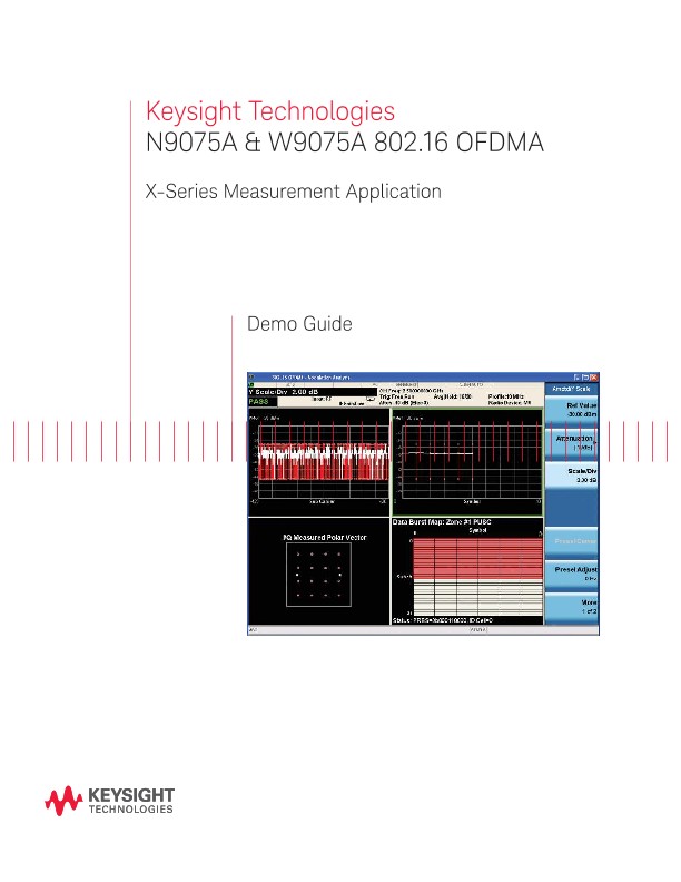
The Keysight Technologies, Inc. N9075A and W9075A 802.16 OFDMA measurement applications provide one-button measurement and modulation analysis capabilities to help your design, evaluation, and manufacturing of Mobile WiMAX™ devices. This demonstration guide follows the list on page 2.
Each demonstration includes a brief description of its function and the corresponding measurement steps on the signal generator and/or signal analyzer.
802.16 OFDMA Test Measurements
– Channel power1
– ACP (adjacent channel power)1
– Spectrum emission mask1
– Spurious emissions
– Occupied bandwidth1
– Power versus time
– Modulation analysis (including spectral flatness)
– Power statistics CCDF
– Monitor spectrum1
– IQ waveform
Demonstration Preparation
All demonstrations use an X-Series signal analyzer and the N5182A MXG vector signal generator. Keystrokes surrounded by [ ] indicate front-panel keys; keystrokes surrounded by { } indicate softkeys located on the display.
Minimum equipment configuration requirements
To configure these instruments, connect the MXG’s 50 RF output to the X-Series signal analyzer’s 50 RF input with a 50 RF cable. Turn on the power in both instruments. Now set up the MXG and Signal Studio for 802.16 WiMAXTM software to generate a OFDMA signal.
Demonstrations
Demonstration 1:
Channel power
Channel power measures and reports the power in the integrated bandwidth as well as computed power spectral density (the power in the signal is normalized to 1 Hz).
You have the ability to adjust the following channel power measurement parameters:
– Integration bandwidth (defaults to 10 MHz)
– Number of trace averages (default to 200)
– Data points displays, 101 to 20001 (default to 1001)
– Configure RRC filter with flexible filter alpha value (default to Off)
– Trigger source: free run, video, line, external-½, RF burst, and periodic timer (default to free run)
– Time gating with gate source: line, external-½, RF burst, and periodic timer (default to periodic timer with sync source = RF burst)
This measurement requires a timing trigger to capture the burst power on period. To measure time-gated spectrum analysis for burst signals, gated LO function is required. With your burst signals, please use any external trigger or gated LO with the X-Series signal analyzer configured by gated LO setups under [Sweep/Control] key.
If you need to measure the OFDMA burst signal and don’t have an external trigger, please use a periodic timer as the gate source with an RF burst as the sync source.
Demonstration 2:
Adjacent channel power (ACP)
This is a measurement for the power present in adjacent transmit channels. The span is set according to the six available offsets and their associate integration bandwidths defined by users or the selected radio standard.
You have the ability to adjust the following adjacent channel power measurement parameters:
– Measure up to 12 carriers for multi-carrier ACP
– Adjust integration bandwidth
– Select up to six channel offsets
– Choose channel offset frequency
– Adjust and display both absolute and relative power
– View bar graph over spectrum trace
– Use built-in averaging detector (RMS) for speed and accuracy
– RRC filter with flexible filter alpha value
– Noise correction On/Off (default to Off)
This measurement requires a timing trigger to capture the burst power on period. To measure time-gated spectrum analysis for burst signals, gated LO function is required.