자세히 알아보기
segmentation:campaign/RF,segmentation:product-category/RF_Testing,segmentation:product-category/RF_Testing/Power_Meters_Sensors,segmentation:business-unit/CSG,keysight:product-lines/wn,segmentation:funnel/bofu,keysight:dtx/solutions/facets/industry/wireless-communications,keysight:dtx/solutions/facets/development-area/rf,keysight:dtx/solutions/facets/workflow-stage/functional-test,keysight:dtx/solutions/facets/design-and-test-product/meter,keysight:models/u2/u2000asegmentation:campaign/RF,segmentation:product-category/RF_Testing,segmentation:product-category/RF_Testing/Power_Meters_Sensors,segmentation:business-unit/CSG,keysight:product-lines/wn,segmentation:funnel/bofu,keysight:dtx/solutions/facets/industry/wireless-communications,keysight:dtx/solutions/facets/development-area/rf,keysight:dtx/solutions/facets/workflow-stage/functional-test,keysight:dtx/solutions/facets/design-and-test-product/meter,keysight:models/u2/u2000asegmentation:campaign/RF,segmentation:product-category/RF_Testing,segmentation:product-category/RF_Testing/Power_Meters_Sensors,segmentation:business-unit/CSG,keysight:product-lines/wn,segmentation:funnel/bofu,keysight:dtx/solutions/facets/industry/wireless-communications,keysight:dtx/solutions/facets/development-area/rf,keysight:dtx/solutions/facets/workflow-stage/functional-test,keysight:dtx/solutions/facets/design-and-test-product/meter,keysight:models/u2/u2000asegmentation:campaign/RF,segmentation:product-category/RF_Testing,segmentation:product-category/RF_Testing/Power_Meters_Sensors,segmentation:business-unit/CSG,keysight:product-lines/wn,segmentation:funnel/bofu,keysight:dtx/solutions/facets/industry/wireless-communications,keysight:dtx/solutions/facets/development-area/rf,keysight:dtx/solutions/facets/workflow-stage/functional-test,keysight:dtx/solutions/facets/design-and-test-product/meter,keysight:models/u2/u2000asegmentation:campaign/RF,segmentation:product-category/RF_Testing,segmentation:product-category/RF_Testing/Power_Meters_Sensors,segmentation:business-unit/CSG,keysight:product-lines/wn,segmentation:funnel/bofu,keysight:dtx/solutions/facets/industry/wireless-communications,keysight:dtx/solutions/facets/development-area/rf,keysight:dtx/solutions/facets/workflow-stage/functional-test,keysight:dtx/solutions/facets/design-and-test-product/meter,keysight:models/u2/u2000asegmentation:campaign/RF,segmentation:product-category/RF_Testing,segmentation:product-category/RF_Testing/Power_Meters_Sensors,segmentation:business-unit/CSG,keysight:product-lines/wn,segmentation:funnel/bofu,keysight:dtx/solutions/facets/industry/wireless-communications,keysight:dtx/solutions/facets/development-area/rf,keysight:dtx/solutions/facets/workflow-stage/functional-test,keysight:dtx/solutions/facets/design-and-test-product/meter,keysight:models/u2/u2000asegmentation:campaign/RF,segmentation:product-category/RF_Testing,segmentation:product-category/RF_Testing/Power_Meters_Sensors,segmentation:business-unit/CSG,keysight:product-lines/wn,segmentation:funnel/bofu,keysight:dtx/solutions/facets/industry/wireless-communications,keysight:dtx/solutions/facets/development-area/rf,keysight:dtx/solutions/facets/workflow-stage/functional-test,keysight:dtx/solutions/facets/design-and-test-product/meter,keysight:models/u2/u2000asegmentation:campaign/RF,segmentation:product-category/RF_Testing,segmentation:product-category/RF_Testing/Power_Meters_Sensors,segmentation:business-unit/CSG,keysight:product-lines/wn,segmentation:funnel/bofu,keysight:dtx/solutions/facets/industry/wireless-communications,keysight:dtx/solutions/facets/development-area/rf,keysight:dtx/solutions/facets/workflow-stage/functional-test,keysight:dtx/solutions/facets/design-and-test-product/meter,keysight:models/u2/u2000asegmentation:campaign/RF,segmentation:product-category/RF_Testing,segmentation:product-category/RF_Testing/Power_Meters_Sensors,segmentation:business-unit/CSG,keysight:product-lines/wn,segmentation:funnel/bofu,keysight:dtx/solutions/facets/industry/wireless-communications,keysight:dtx/solutions/facets/development-area/rf,keysight:dtx/solutions/facets/workflow-stage/functional-test,keysight:dtx/solutions/facets/design-and-test-product/meter,keysight:models/u2/u2000asegmentation:campaign/RF,segmentation:product-category/RF_Testing,segmentation:product-category/RF_Testing/Power_Meters_Sensors,segmentation:business-unit/CSG,keysight:product-lines/wn,segmentation:funnel/bofu,keysight:dtx/solutions/facets/industry/wireless-communications,keysight:dtx/solutions/facets/development-area/rf,keysight:dtx/solutions/facets/workflow-stage/functional-test,keysight:dtx/solutions/facets/design-and-test-product/meter,keysight:models/u2/u2000asegmentation:campaign/RF,segmentation:product-category/RF_Testing,segmentation:product-category/RF_Testing/Power_Meters_Sensors,segmentation:business-unit/CSG,keysight:product-lines/wn,segmentation:funnel/bofu,keysight:dtx/solutions/facets/industry/wireless-communications,keysight:dtx/solutions/facets/development-area/rf,keysight:dtx/solutions/facets/workflow-stage/functional-test,keysight:dtx/solutions/facets/design-and-test-product/meter,keysight:models/u2/u2000a
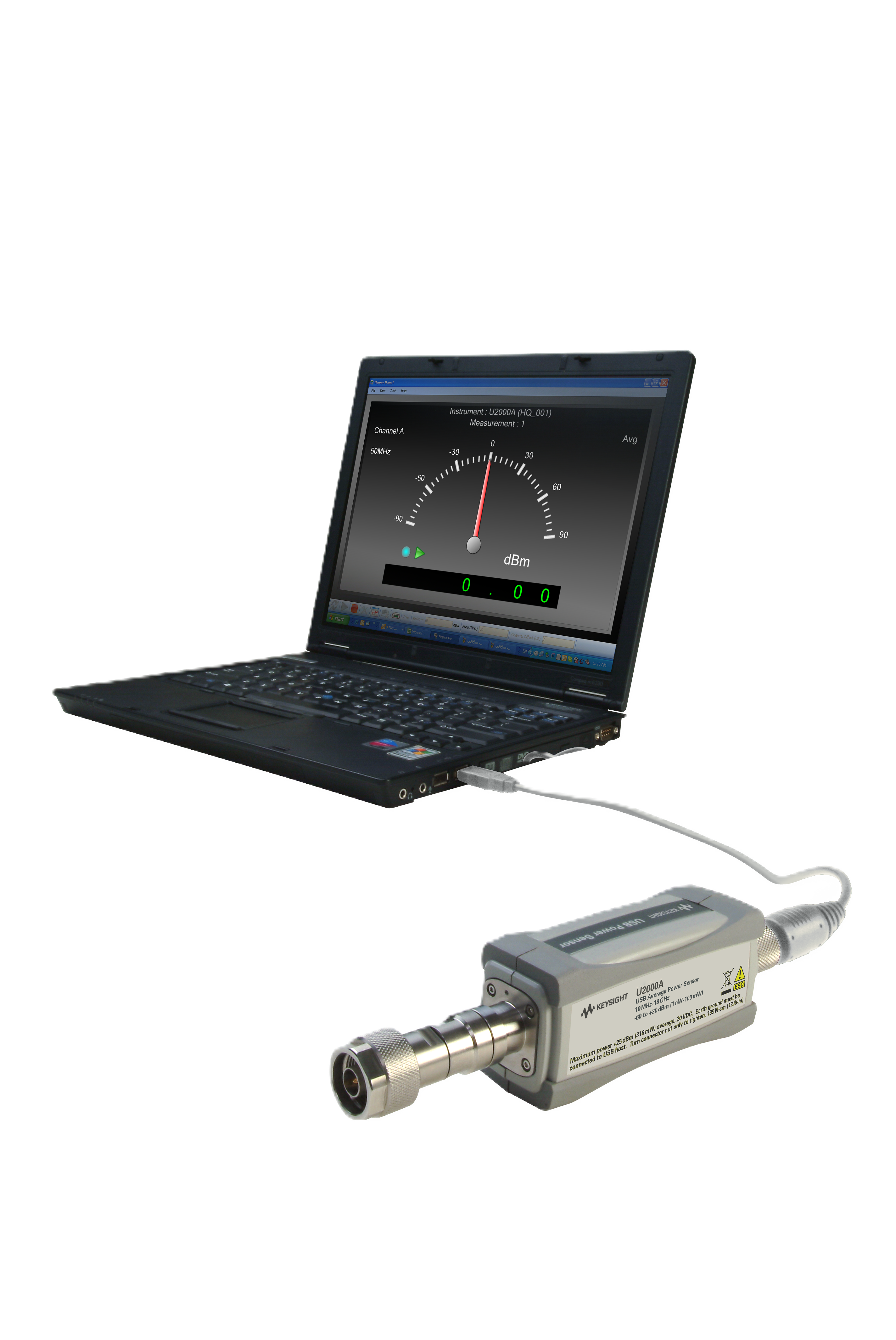
PC에서 직접 RF 전력 측정을 자동화하는 방법
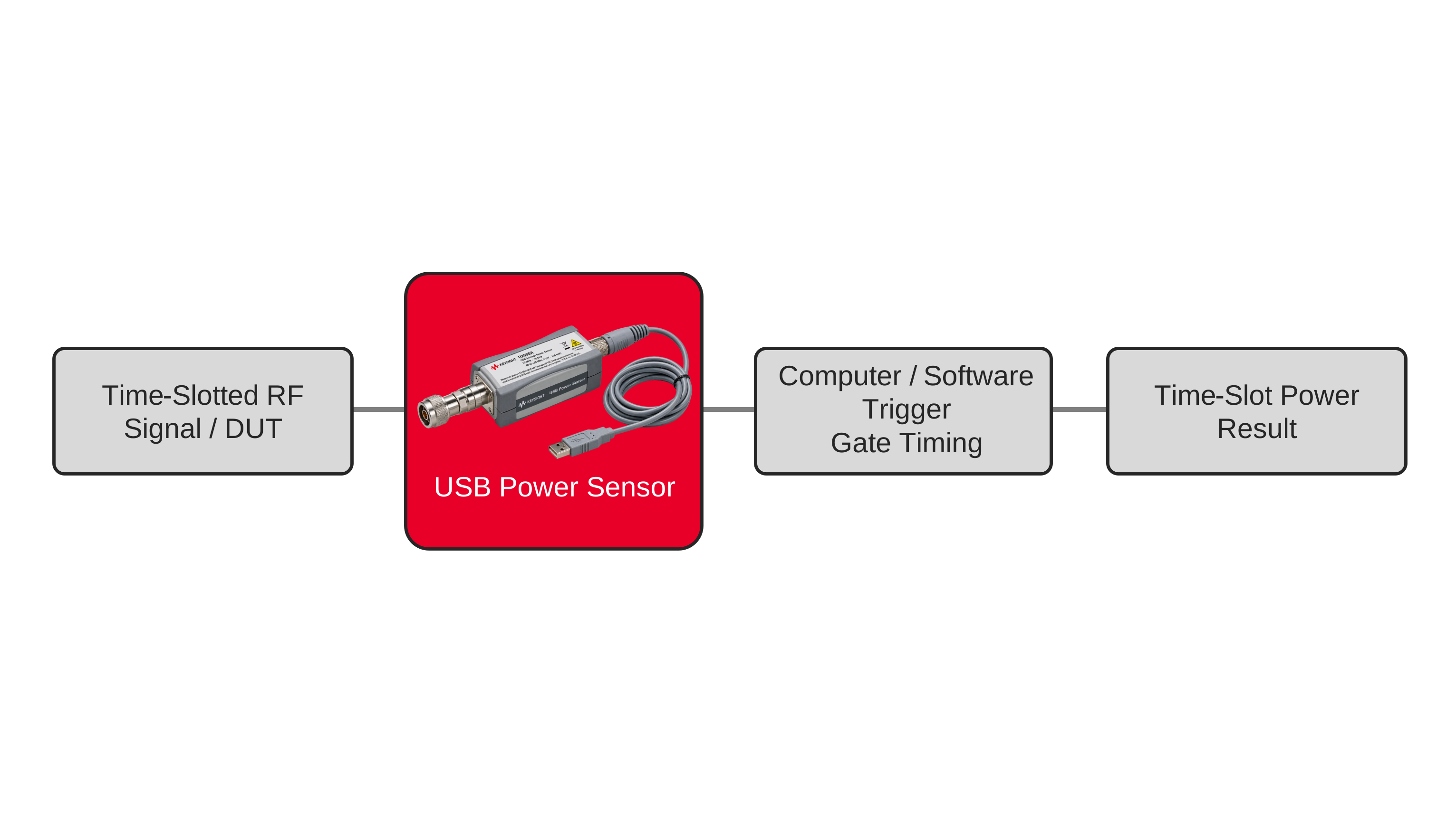
USB 전력 센서, 소프트웨어 제어, 데이터 로깅 및 프로그래밍 가능한 테스트 시퀀스를 활용하여 PC에서 직접 무선 주파수 전력 측정을 자동화합니다.
자세히 알아보기