
M5400PLSA Quantum Library Dynamic Pulse Generation
Data Sheets
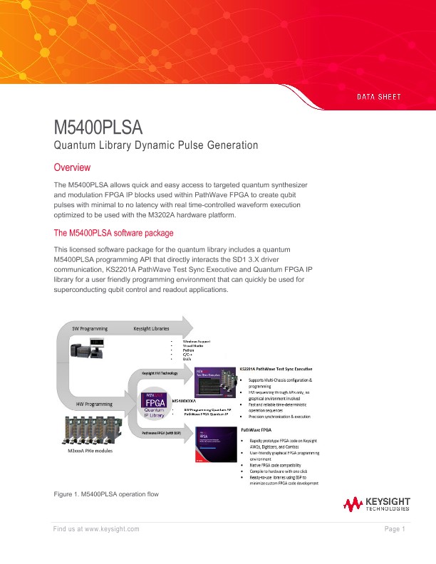
Overview
The M5400PLSA allows quick and easy access to targeted quantum synthesizer and modulation FPGA IP blocks used within PathWave FPGA to create qubit pulses with minimal to no latency with real time-controlled waveform execution optimized to be used with the M3202A hardware platform.
The M5400PLSA software package
This licensed software package for the quantum library includes a quantum M5400PLSA programming API that directly interacts the SD1 3.X driver communication, KS2201A PathWave Test Sync Executive and Quantum FPGA IP library for a user friendly programming environment that can quickly be used for superconducting qubit control and readout applications.
Using the fully integrated software and FPGA Gateware package allows for simplifying your configuration and provides massive savings of development time to integrate and expand to multi qubit systems including multi-chassis configurations for scaling system configurations.
Features
The quantum FPGA IP provides ultra-light weight and scalable components that have a small FPGA footprint that allows for 0ns latency pulse waveform execution and play using precise real-time control through PathWave Test Sync Executive technology known as HVI, hardware virtual instrument. The convenient quantum FPGA IP also provides the ability to phase lock to the M3102A Digitizer through HVI. Using precise real-time control allows for deterministic phase coherent simultaneous waveform selection and triggering of launching arbitrary pulse waveforms with no latency nor requires pre-determined order of waveform playing.
• GaplessAgileAWG - Dual Port Digital synthesizer with programmable memory length to accommodate custom configurations of waveform length for up to 64 waveforms with dynamic length allocation if not all 64 waveforms are defined. Convenient and flexible for qubit pulse generation for readout and control applications.
• DUC - Digital Up Converter for applying amplitude and phase modulation to the waveform synthesizer outputs with the convenience to create real time control of amplitude, phase, offset and frequency to modulated outputs for qubit readout and control applications.
• QuWaveControl used to provide easy control to launch waveforms independently or simultaneously across all channels controlled all through a HVI sequence, host software or PXI trigger hardware interface.
Table 1-1: Technical Performance Specifications (IP Components)
IP Component |
|
|
Nominal Characteristics |
|
||
|
Parameter |
Min. |
Typ. |
Max. |
Units |
Comments |
GaplessAgileAWG |
|
|
|
|||
|
Waveform Port A |
|
160 |
|
bits |
Data output width compatible with DUC awgAngle input. Normalized real phase, complex I quadrature, or complex polar phase |
Waveform Port B |
|
80 |
|
bits |
Data output width compatible with DUC awgAmplitude input. Normalized real amplitude, complex Q quadrature, or complex polar amplitude |
|
Waveforms |
1 |
|
64 |
waveforms/port |
6-bit decode waveform selection to scale up to 64 selectable waveforms |
|
Memory Address Size |
11 |
14 |
16 |
bits |
address width to specify memory size. Applied to both waveform ports settable in PathWave FPGA instantiation parameter |
|
Max Memory Samples |
10,240 |
81,920 |
327,680 |
samples/port |
per Memory Address. Size setting |
|
IP Component |
Nominal Characteristics |
|||||
|
Max Waveform Samples |
160 |
1,280 |
5,120 |
samples/max waveforms |
per Memory Address. Size setting and all 64 waveforms specified |
Minimum Waveform Sample Size |
10 |
10 |
10 |
Samples |
10ns length. See Nominal Characteristics. Sampling Clock. (Comments in the section below.) |
|
Output Latency |
|
0 |
|
ns |
from waveform selection trigger event using QuWaveControl |
|
Buffered Early Waveform Selection / Trigger Event |
|
1 |
|
trigger |
allows for single buffered waveform selection trigger event. Executes 0ns after current waveform execution completes. |
|
Re-arm time |
|
0 |
|
ns |
allows for gapless waveform generation using HVI instruction. No real-time HVI phase, amplitude, frequency within seq. |
|
DUC |
|
|||||
|
Amplitude |
-1.5 |
|
1.5 |
volts |
amplitude of modulating signal. Control via Quantum Library API or HVI instructions. |
DC Offset |
-1.5 |
|
1.5 |
volts |
dc offset of modulating signal. Control via Quantum Library API or HVI instructions. |
|
IP Component |
|
|
No |
minal Characteristics |
||
|
Parameter |
Min. |
Typ. |
Max. |
Units |
Comments |
|
Frequency |
-400 |
|
400 |
MHz |
frequency of modulating signal. Control via Quantum Library API or HVI instructions |
Phase |
-180 |
|
180 |
degrees |
phase of modulating signal. Control via Quantum Library API or HVI instructions |
|
QuWaveControl |
|
|
|
|
||
|
Number of Waveform Control Ports |
|
4 |
|
waveform selection and auto trigger |
Individually programmable to control independently or simultaneously for waveform generation across channels |
|
Waveform Selection |
|
6 |
|
bits |
6-bit decode for 64 waveforms |
|
Auto Trigger |
|
1 |
|
bit / waveform selection |
1-bit auto trigger generated upon executing waveform selection command either HVI or SW host |
|
PXI Trigger |
|
1 |
|
bit / waveform selection |
1-bit auto trigger event from PXI Trigger rising edge event |
|
Waveform Selection Options |
|
3 |
|
interfaces |
HVI, SW Host or PXI Triggers for waveform selection interfaces supported |