What are you looking for?
Oscilloscope Probes Selection Guide
Get the measurement accuracy you want for your application

Probe Types
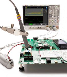
Keysight offers a broad range of voltage, current, and optical probing solutions for InfiniiVision and Infiniium Series oscilloscopes. Select from the probe categories listed below to see what Keysight has to offer.

Passive Probes
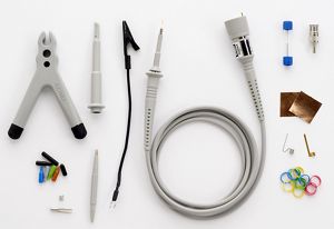
Keysight offers a broad range of passive probes with various attenuation ratios and input impedance specifications to optimize the dynamic range and loading considerations of your oscilloscope ground-reference measurements. These passive probes are compatible with most Keysight oscilloscopes that have either standard BNC inputs or AutoProbe1/BNC input connections.

| General-Purpose Passive Probes | |||||
|---|---|---|---|---|---|
| Model | Bandwidth | Attenuation Ratio | Input Impedance1 | Compensation Range2 | Notes |
| N2840A | 50 MHz | 10:1 | 10 MΩ // 11 pF | 5 - 30 pF | |
| 10074D | 150 MHz | 10:1 | 10 MΩ // 15 pF | 9 - 17 pF | |
| N2841A | 150 MHz | 10:1 | 10 MΩ // 11 pF | 5 - 30 pF | Recommended for InfiniiVision 2000 X-Series |
| N2871A | 200 MHz | 10:1 | 10 MΩ // 9.5 pF | 10 - 25 pF | Optimized for fine-pitch probing |
| N2842A | 300 MHz | 10:1 | 10 MΩ // 11 pF | 5 - 30 pF | Recommended for InfiniiVision 2000 X-Series |
| N2853A | 350 MHz | 10:1 | 10 MΩ // 11 pF | 5 - 30 pF | |
| N2872A | 350 MHz | 10:1 | 10 MΩ // 9.5 pF | 10 -25 pF | Optimized for fine-pitch probing |
| N7007A | 400 MHz | 10:1 | 10 MΩ // 16 pF | 6 - 18 pF | Extreme temperature probing (-40 to +85°C), 2 meter cable |
| N2843A | 500 MHz | 10:1 | 10 MΩ // 11 pF | 5 - 30 pF | Recommended for InfiniiVision 3000 X-Series |
| 10073D | 500 MHz | 10:1 | 2.2 MΩ // 12 pF | 6 - 15 pF | |
| N2873A | 500 MHz | 10:1 | 10 MΩ // 9.5 pF | 10-25 pF | Fine-pitch, recommended for Infiniium EXR/MXR/S-Series |
| N2875A | 500 MHz | 20:1 | 20 MΩ // 5.6 pF | 7 - 20 pF | Optimized for fine-pitch, low-capacitive probing |
| N2894A | 700 MHz | 10:1 | 10 MΩ // 9.5 pF | 10 - 25 pF | Fine-pitch, recommended for InfiniiVision 4000/6000 X-Series |
| PP0002A | 800 MHz | variable | 40 MΩ // 2.0 pF | N/A | 5 mm tip, 1200 V CAT II, requires PP0004A (AutoProbe 1) |
| PP0001A | 1 GHz | variable | 10 MΩ // 4.0 pF | N/A | 5 mm tip, 300 V CAT II, requires PP0004A (AutoProbe 1) |
| PP0003A | 1 GHz | variable | 10 MΩ // 4.0 pF | N/A | MMCX connector, 30 V CAT II, requires PP0004A (AutoProbe 1) |
| Switchable Passive Probes (1:1 // 10:1) | |||||
|---|---|---|---|---|---|
| Model | Bandwidth | Attenuation Ratio | Input Impedance1,3 | Compensation Range2 | Notes |
| N2142A | 6 MHz | 1:1 | 1 MΩ // 100 pF + | N/A | Low-cost 2-pack, recommended for InfiniiVision EDUX1000 X-Series |
| 70 MHz | 10:1 | 10 MΩ // 15 pF + | 15 - 30 pF | ||
| N2140A | 6 MHz | 1:1 | 1 MΩ // 100 pF + | N/A | Low-cost 2-pack, recommended for InfiniiVision EDUX1000 X-Series |
| 200 MHz | 10:1 | 10 MΩ // 15 pF + | 15 - 30 pF | ||
| N2889A | 10 MHz | 1:1 | 1 MΩ // 60 pF + | N/A | The most general-purpose passive probe |
| 350 MHz | 10:1 | 10 MΩ // 11 pF + | 10 - 35 pF | ||
| High-voltage Passive Probe (100:1) | |||||
|---|---|---|---|---|---|
| Model | Bandwidth | Atten. Ratio | Input Impedance1 | Compensation Range2 | Notes |
| 10076C | 500 MHz | 100:1 | 66.7 MΩ // 3 pF + | 6 - 18 pF | High-voltage, low capacitive probing |
| High-frequency/Low-Z Passive Probes (50-Ω terminated) | |||||
|---|---|---|---|---|---|
| Model | Bandwidth | Attenuation Ratio | Input Impedance4 | Compensation Range | Notes |
| N2874A | 1.5 GHz | 10:1 | 500 Ω // 1.8 pF + | N/A | Low-cost, high-frequency probing at the cost of resistive loading |
| N2876A | 1.5 GHz | 100:1 | 5 kΩ // 2.2 pF + | N/A | Low-cost, high-frequency probing at the cost of resistive loading |
1. Input impedance when terminated into oscilloscopes with 1-MΩ input terminations. For higher-bandwidth Infiniium oscilloscopes with 50-Ω input terminations only, the E2697A high impedance adapter can be purchased (includes 10073D 500-MHz passive probe) to provide a 1-MΩ input termination.
2. For proper probe compensation (flatness), the oscilloscope’s input capacitance must be within the specified compensation range of the probe.
3. Capacitance at the probe tip of 1:1 probes is the specified probe capacitance plus the capacitance of the oscilloscope when terminated into 1-MΩ.
4. Input impedance when terminated into oscilloscopes with 50-Ω input terminations. These probes are not compatible with Keysight’s InfiniiVision 1000 and 2000 X-Series oscilloscopes.
Optically Isolated Differential Probes
Galvanically isolated voltage probes separate the device under test (DUT) from the oscilloscope and earth ground, enabling safer and more accurate measurements. These types of probes have a high common-mode rejection ratio (CMRR), which is essential for capturing small signals in the presence of large common-mode voltages at floating nodes. Keysight's isolated probes have a CMRR up to 10 billion times higher than standard differential voltage probes referenced to earth ground. The CMRRs of Keysight's isolated probes are driven by the attached probe tip.


| Optically Isolated Differential Probes | |||||||
|---|---|---|---|---|---|---|---|
| Model | Bandwidth | Max Input Range1 | Max Probe Offset | Max Common Mode Voltage Range | Prob-to-scope Interface | Power Source | Oscilloscope Termination |
| PS0004A | 350 MHz | ±2500 V | ±2500 V | ±60 kV | AutoProbe1 | Oscilloscope | 50 Ω |
| PS0006A | 700 MHz | ±2500 V | ±2500 V | ±60 kV | AutoProbe1 | Oscilloscope | 50 Ω |
| PS0008A | 1 GHz | ±2500 V | ±2500 V | ±60 kV | AutoProbe1 | Oscilloscope | 50 Ω |
- Probe tip dependent. View the compatible tips on the probe model web pages.
| Oscilloscope Compatibility for Optically Isolated Differential Probes | ||
|---|---|---|
| Probe-to-scope Interface | Scope Termination | Compatible Oscilloscopes |
AutoProbe1 | 50 Ω | Infiniium EXR and MXR-Series |
AutoProbe Interface
Keysight’s AutoProbe interface provides the following:
- DC voltage to power active probe circuitry.
- Automatic detection of probe attenuation.
- Automatic control of selectable probe attenuation on some probes.
- Probe DC offset on many probes.
Differential Active Probes < 10 GHz
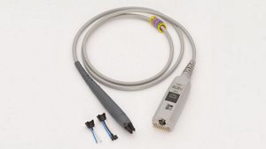
Probing high-speed differential buses typically requires differential active probes. Keysight offers a broad range of differential active probing solutions for your unique measurement requirements based on bandwidth, dynamic measurement range, and probe loading.

| Differential Active Probes < 10 GHz | ||||||||
|---|---|---|---|---|---|---|---|---|
| Model | Bandwidth | Input Range | Probe Offset | Diff Input Impedance | Attenuation Ratio | Prob-to-scope Interface | Power Source | Oscilloscope Termination |
| N2750A | 1.5 GHz | ±5 V | ±15 V | 100 kΩ/0.7 pF | 2:1/10:11 | AutoProbe1 | Oscilloscope | 50 Ω |
| N2751A | 3.5 GHz | ±5 V | ±15 V | 100 kΩ/0.7 pF | 2:1/10:11 | AutoProbe1 | Oscilloscope | 50 Ω |
| N2752A | 6.0 GHz | ±5 V | ±15 V | 100 kΩ/0.7 pF | 2:1/10:11 | AutoProbe1 | Oscilloscope | 50 Ω |
| 1130B2 | 1.5 GHz | ±2.5 V | ±12 V | 50 kΩ/0.27 pF | 10:1 | AutoProbe1 | Oscilloscope | 50 Ω |
| 1131B2 | 3.5 GHz | ±2.5 V | ±12 V | 50 kΩ/0.27 pF | 10:1 | AutoProbe1 | Oscilloscope | 50 Ω |
| 1132B2 | 6.0 GHz | ±2.5 V | ±12 V | 50 kΩ/0.27 pF | 10:1 | AutoProbe1 | Oscilloscope | 50 Ω |
| 1134B2 | 7.0 GHz | ±2.5 V | ±12 V | 50 kΩ/0.27 pF | 10:1 | AutoProbe1 | Oscilloscope | 50 Ω |
| N2830A2,3 | 4 GHz | ±2.5 V | ±16 V | 100 kΩ/0.32 pF | 5:1/10:11 | AutoProbe1 | Oscilloscope | 50 Ω |
| N2831A2,3 | 8 GHz | ±2.5 V | ±16 V | 100 kΩ/0.32 pF | 5:1/10:11 | AutoProbe1 | Oscilloscope | 50 Ω |
| N7000A2 | 8 GHz | ±2.5 V | ±16 V | 100 kΩ/0.32 pF | 5:1/10:11 | AutoProbe2 | Oscilloscope | 50 Ω |
| Oscilloscope Compatibility for High-Frequency Differential Active Probes (<10 GHz) | ||
|---|---|---|
| Probe-to-scope Interface | Scope Termination | Compatible Oscilloscopes |
| BNC | 50 Ω |
|
| AutoProbe1 | 50 Ω |
|
| AutoProbe2 | 50 Ω |
|
AutoProbe Interface
Keysight’s AutoProbe interface provides the following:
- DC voltage to power active probe circuitry
- Automatic detection of probe attenuation
- Automatic control of selectable probe attenuation on some probes
- Probe DC offset on many probes
High-Frequency Differential Active Probes ≥ 10 GHz
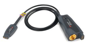
Get the highest performance available for measuring differential and single-ended signals on high-density integrated circuits and printed circuit boards.
As devices get smaller and faster, accurately probing signals becomes more challenging. Keysight’s InfiniiMax Probing System has the most accurate probe amplifiers, the widest variety of probe heads, and all the accessories you need to get the job done.

| High-Frequency Differential Active Probes ≥ 10 GHz | |||||||||
|---|---|---|---|---|---|---|---|---|---|
| Model | Bandwidth | Impedance Profile1 | Diff Input Impedance | Probe Noise2 | Probe-to-Scope Interface | InfiniiMode3 | Input Range | Probe Offset | Attenuation Range4 |
| MX0032A | 52 GHz (B-T 40 GHz) | RCRC | 100 kΩ/ 0.32 pF | 27.1 nV/ rt(Hz) | AutoProbe3 | No | ±1 V | ±12 V | 4.4:1/ 8.7:1 |
| MX0031A | 52 GHz | RCRC | 100 kΩ/ 0.32 pF | 27.1 nV/ rt(Hz) | AutoProbe3 | No | ±1 V | ±12 V | 4.4:1/ 8.7:1 |
| MX0030A | 42 GHz | RCRC | 100 kΩ/ 0.32 pF | 27.1 nV/ rt(Hz) | AutoProbe3 | No | ±1 V | ±12 V | 4.4:1/ 8.7:1 |
| N2803A | 30 GHz | RCRC | 100 kΩ /0.32 pF | 23.9 nV/rt(Hz) | AutoProbe2 | No | ±1.25 V | ±16 V | 6:1 |
| MX0025A | 25 GHz | RC | 50 kΩ/0.17 pF | 25.0 nV/rt(Hz) | AutoProbe2 | Yes | ±2.5 V | ±16 V | 1:1/4:1/8:1 |
| MX0023A | 25 GHz | RC | 50 kΩ/0.17 pF | 25.0 nV/rt(Hz) | AutoProbe2 | No | ±1.25 V | ±16 V | 1:1/4:1 |
| N2802A | 25 GHz | RCRC | 100 kΩ /0.32 pF | 23.9 nV/rt(Hz) | AutoProbe2 | No | ±1.25 V | ±16 V | 6:1 |
| MX0024A | 20 GHz | RC | 50 kΩ/0.17 pF | 25.0 nV/rt(Hz) | AutoProbe2 | Yes | ±2.5 V | ±16 V | 1:1/4:1/8:1 |
| N2801A | 20 GHz | RCRC | 100 kΩ /0.32 pF | 23.9 nV/rt(Hz) | AutoProbe2 | No | ±1.25 V | ±16 V | 6:1 |
| N7003A | 20 GHz | RCRC | 100 kΩ /0.32 pF | 33.5 nV/rt(Hz) | AutoProbe2 | Yes | ±2.5 V | ±16 V | 5:1/10:1 |
| MX0022A | 16 GHz | RC | 50 kΩ/0.17 pF | 25.0 nV/rt(Hz) | AutoProbe2 | Yes | ±2.5 V | ±16 V | 1:1/4:1/8:1 |
| N7002A | 16 GHz | RCRC | 100 kΩ /0.32 pF | 33.5 nV/rt(Hz) | AutoProbe2 | Yes | ±2.5 V | ±16 V | 5:1/10:1 |
| MX0021A | 13 GHz | RC | 50 kΩ/0.17 pF | 25.0 nV/rt(Hz) | AutoProbe2 | Yes | ±2.5 V | ±16 V | 1:1/4:1/8:1 |
| N7001A | 13 GHz | RCRC | 100 kΩ /0.32 pF | 33.5 nV/rt(Hz) | AutoProbe2 | Yes | ±2.5 V | ±16 V | 5:1/10:1 |
| N2832A | 13 GHz | RCRC | 100 kΩ /0.32 pF | 33.5 nV/rt(Hz) | AutoProbe1 | Yes | ±2.5 V | ±16 V | 5:1/10:1 |
| 1169B | 13 GHz | RC | 50 kΩ /0.21 pF | 25.0 nV/rt(Hz) | AutoProbe1 | No | ±1.65 V | ±16 V | 3.45:1 |
| MX0020A | 10 GHz | RC | 50 kΩ/0.17 pF | 25.0 nV/rt(Hz) | AutoProbe2 | Yes | ±2.5 V | ±16 V | 1:1/4:1/8:1 |
| 1168B | 10 GHz | RC | 50 kΩ /0.21 pF | 25.0 nV/rt(Hz) | AutoProbe1 | No | ±1.65 V | ±16 V | 3.45:1 |
1. Input Impedance Profile: RCRC architecture is the best choice for signals with low source impedance and RC architecture is the best choice for measuring signals that transition to low power modes because it has lower loading.
2. Probe noise listed is the most common setup. Probe noise can vary with multiple factors such as attenuation ratio, probe head, and probe mode.
3. Measure differential, single-ended, and common mode signals.
4. Auto selected based on volts/division (all modes).
| Oscilloscope Compatibility for High-Frequency Differential Active Probes ≥ 10 GHz | |
|---|---|
| Probe-to-scope Interface | Compatible Oscilloscopes |
| AutoProbe1 | Infiniium MXR, EXR, S-Series, 9000, and 90000A Series Infiniium UXR (3.5 mm models), V, Z, Q, and 90000X Series with the use of the N5442A adapter Infiniium UXR (1.85 mm and 1 mm models) with the cascaded use of the N5442A & N2852A adapters |
| AutoProbe2 | Infiniium UXR (3.5 mm models), V, Z, Q, and 90000X Series Infiniium UXR (1.85 mm and 1 mm models) with the use of the N2852A adapter Infiniium N1000A and 86100D DCA-X with the use of the N5477A adapter (only for N2801A/02A/03A) |
| AutoProbe3 | Infiniium UXR (1.85 mm and 1 mm models) |
High-Voltage Differential Active Probes
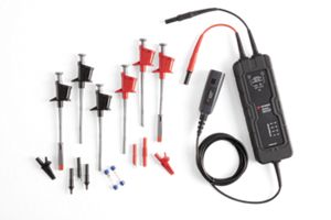
Keysight offers a broad range of high-voltage differential probes to help test power-related devices and circuits including probes with high input impedance for minimal loading, probes with multiple attenuation ratios for optimum dynamic range measurements, and probes that can measure up to ±7000 Volts.

| High-Voltage Differential Active Probes | |||||||
|---|---|---|---|---|---|---|---|
| Model | Bandwidth | Input Range | Diff Input Impedance | Attenuation Ratio | Prob-to-scope Interface | Power Source | Oscilloscope Termination |
| N2805A | 200 MHz | ±100 V | 4 MΩ/4.0 pF | 50:1 | AutoProbe1 | Oscilloscope | 50 Ω |
| N2804A | 300 MHz | ±300 V | 8 MΩ/10 pF | 100:1 | AutoProbe1 | Oscilloscope | 50 Ω |
| N2790A | 100 MHz | ±1400 V | 1 MΩ/3.5 pF | 50:1/500:1 | AutoProbe1 | Oscilloscope | 1 MΩ |
| DP0001A | 400 MHz | ±2000 V | 10 MΩ/2.0 pF | 50:1/100:1/250:1/500:1 | AutoProbe1 | Oscilloscope | 50 Ω |
| DP0010A | 250 MHz | ±42 V | 1.7 MΩ/0.9 pF | 17:1/85:1 | AutoProbe1 | Oscilloscope | 50 Ω |
| DP0011A | 500 MHz | ±42 V | 1.7 MΩ/0.9 pF | 17:1/85:1 | AutoProbe1 | Oscilloscope | 50 Ω |
| DP0012A | 1.0 GHz | ±42 V | 1.7 MΩ/0.9 pF | 17:1/85:1 | AutoProbe1 | Oscilloscope | 50 Ω |
| DP0013A | 1.7 Ghz | ±42 V | 1.7 MΩ/0.9 pF | 17:1/85:1 | AutoProbe1 | Oscilloscope | 50 Ω |
| DP0030A | 100 MHz | ±750 V | 5 MΩ // 2 pF | 250/25:1 | BNC | USB | 1 MΩ |
| DP0031A | 200 MHz | ±750 V | 5 MΩ // 2 pF | 250/25:1 | AutoProbe1 | Oscilloscope | 1 MΩ |
| DP0032A | 200 MHz | ±1500 V | 10 MΩ // 2 pF | 500/50:1 | AutoProbe1 | Oscilloscope | 1 MΩ |
| DP0033A | 200 MHz | ±3000 V | 20 MΩ // 2 pF | 1000/100:1 | AutoProbe1 | Oscilloscope | 1 MΩ |
| Oscilloscope Compatibility for High-Voltage Differential Active Probes | ||
|---|---|---|
| Probe-to-scope Interface | Oscilloscope Termination | Compatible Oscilloscopes |
| BNC | 1 MΩ |
|
| BNC | 50 Ω |
|
| AutoProbe11 | 50 Ω | |
1. DP0001A is not compatible with the InfiniiVision 3000A X-Series oscilloscopes.
AutoProbe1 Interface
Keysight’s AutoProbe1 interface provides the following:
- DC voltage to power active probe circuitry
- Automatic detection of probe attenuation
- Automatic control of selectable probe attenuation on some probes
- Probe DC offset on many probes
Single-Ended Active Probes
Measurements Referenced to Ground
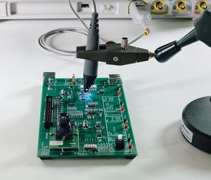
When capacitive loading and limited bandwidth of conventional passive probes begin to degrade the measurement integrity of your high-speed signals, consider using one of Keysight’s higher bandwidth single-ended active probes.

| Single-Ended Active Probes | |||||||
|---|---|---|---|---|---|---|---|
| Model | Bandwidth | Input Range | Probe Offset | Input Impedance | Attenuation Ratio | Probe-to-scope Interface | Notes |
| N2795A | 1 GHz | ±8 V | ±8 V | 1 MΩ/1.0 pF | 10:1 | AutoProbe1 | |
| N2797A | 1.5 GHz | ±8 V | ±12 V | 1 MΩ/1.0 pF | 10:1 | AutoProbe1 | Extreme Temp. (-40 to +85° C), 2 meter long cable |
| N2796A | 2 GHz | ±8 V | ±12 V | 1 MΩ/1.0 pF | 10:1 | AutoProbe1 | |
| 1130B1 | 1.5 GHz | ±2.5 V | ±12 V | 25 kΩ/0.44 pF | 10:1 | AutoProbe1 | |
| 1131B1 | 3.5 GHz | ±2.5 V | ±12 V | 25 kΩ/0.44 pF | 10:1 | AutoProbe1 | |
| 1132B1 | 5.0 GHz | ±2.5 V | ±12 V | 25 kΩ/0.44 pF | 10:1 | AutoProbe1 | |
| 1134B1 | 7.0 GHz | ±2.5 V | ±12 V | 25 kΩ/0.44 pF | 10:1 | AutoProbe1 | |
- Single-ended and differential probe. Requires probe head sold separately.
| Oscilloscope Compatibility for Single-Ended Active Probes | |
|---|---|
| Probe-to-scope Interface | Compatible Oscilloscopes |
| AutoProbe1 |
|
AutoProbe1 Interface
Keysight’s AutoProbe1 interface provides the following:
- DC voltage to power active probe circuitry
- Automatic detection of probe attenuation
- Automatic control of selectable probe attenuation on some probes
- Probe DC offset on many probes
Power Rail Probes
Measure Output Ripple with High-Sensitivity
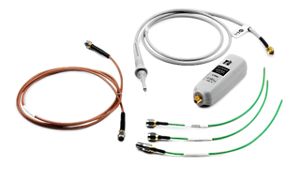
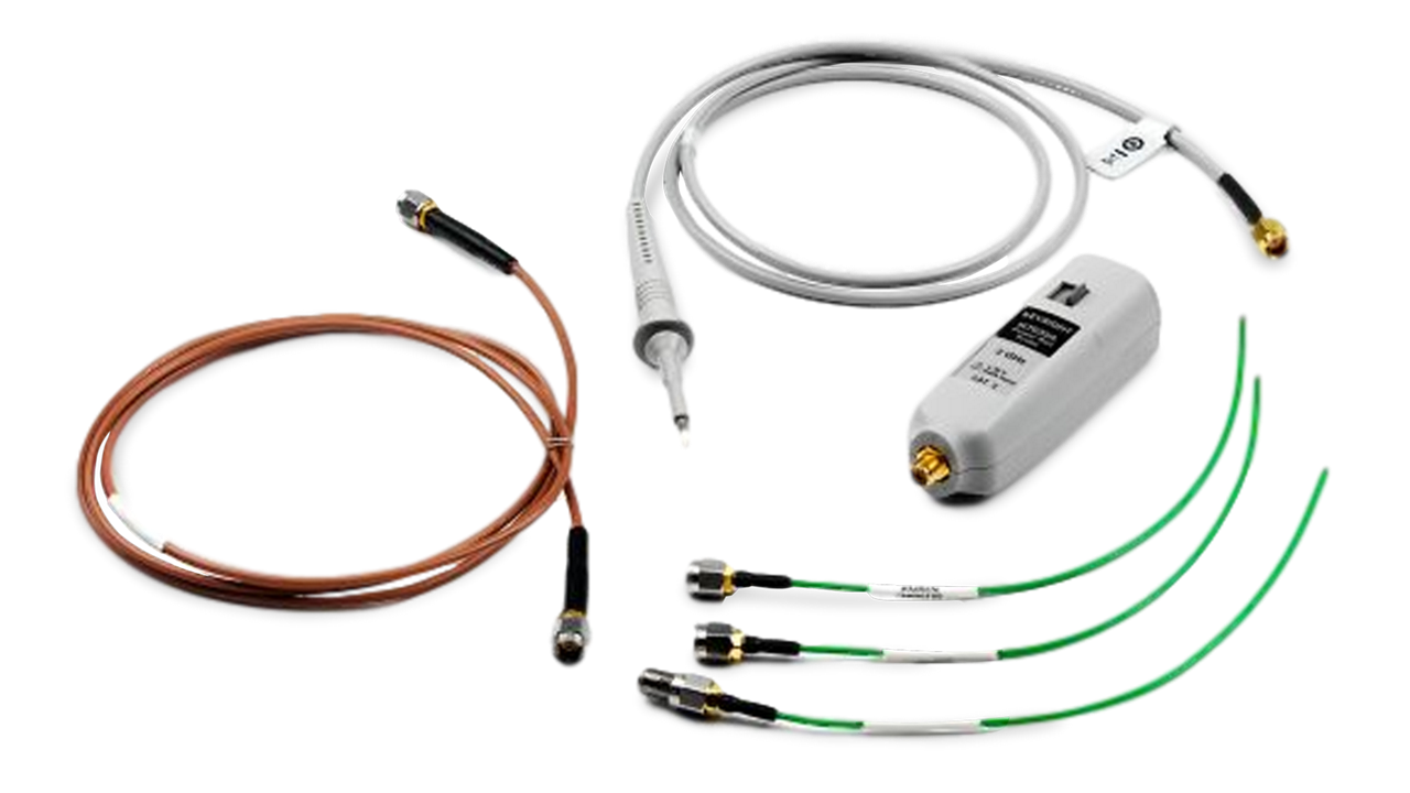
Engineers often use 1:1 passive probes for the sensitivity required to measure the output ripple of DC supplies. But 1:1 passive probes have limited bandwidth (typically less than 35 MHz) and no DC offset capability. A Keysight power rail probe can measure noise, output ripple, and transients on DC power supplies with high sensitivity (millivolts), large DC offsets, and high bandwidth.
- Measurement range about offset level.
| Oscilloscope Compatibility for Power Rail Probes | |
|---|---|
| Model | Compatible Oscilloscopes |
| N7020A |
|
| N7024A |
|
AutoProbe1 Interface
Keysight’s AutoProbe1 interface provides the following:
- DC voltage to power active probe circuitry
- Automatic detection of probe attenuation
- Automatic control of selectable probe attenuation on some probes
- Probe DC offset on many probes
Current Probes
Keysight offers a broad range of current probing solutions including clamp-on current probes with bandwidths from DC to 150 MHz, Rogowski coils that can measure peak currents up to 3000 Amps, and high-sensitivity R-shunt probes that can measure current as low as 50 µA.
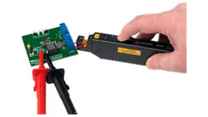

| AC/DC Hall-Effect (Clamp-On) Current Probes | ||||||
|---|---|---|---|---|---|---|
| Model | Bandwidth | Max Current | Conversion Factor (Attenuation) | Min Scope Vertical Scale | Probe-to-Scope Interface | Power Source |
| N7026A | 150 MHz | 40 A-Pk1, 30 A-RMS1 | 1 V/A (1:1), 0.2 V/A (5:1)2 | 1 mA/div | AutoProbe1 | Oscilloscope |
| N2893A | 100 MHz | 30 A-Pk3, 24 A-RMS3 | 0.1 V/A (10:1) | 10 mA/div | AutoProbe1 | Oscilloscope |
| N2783B | 100 MHz | 50 A-Pk, 30 A-RMS | 0.1 V/A (10:1) | 10 mA/div | BNC | N2779A |
| 1147B | 50 MHz | 30 A-Pk3, 24 A-RMS3 | 0.1 V/A (10:1) | 10 mA/div | AutoProbe1 | Oscilloscope |
| N2782B | 50 MHz | 50 A-Pk, 30 A-RMS | 0.1 V/A (10:1) | 10 mA/div | BNC | N2779A |
| N2781B | 10 MHz | 300 A-Pk, 150 A-RMS | 0.01 V/A (100:1) | 100 mA/div | BNC | N2779A |
| N2780B | 2 MHz | 700 A-Pk, 500 A-RMS | 0.01 V/A (100:1) | 100 mA/div | BNC | N2779A |
| 1146B | 100 kHz | 100 A-Pk, 100 A-RMS | 0.1 V/A (10:1), 0.01 V/A (100:1)4 | 10 mA/div | BNC | 9 V Battery |
| AC-Only Rogowski Current Probes | |||||
|---|---|---|---|---|---|
| Model | Bandwidth | Max Current | Conversion Factor (Attenuation) | Probe-to-Scope Interface | Power Source |
| N7042A | 9.2 Hz- 30 MHz | 300 A-Pk | 0.02 V/A (50:1) | BNC | AC power adapter or 4x AA batteries |
| N7041A | 12 Hz - 30 MHz | 600 A-Pk | 0.01 V/A (100:1) | BNC | AC power adapter or 4x AA batteries |
| N7040A | 3 Hz - 23 MHz | 3000 A-Pk | 0.002 V/A (500:1) | BNC | AC power adapter or 4x AA batteries |
| High-Sensitivity AC/DC R-Shunt Current Probes | |||||||
|---|---|---|---|---|---|---|---|
| Model | Bandwidth | Current Range5 | Gain | Channels | Probe Heads (Standard) | Probe-to-Scope Interface | Power Source |
| N2820A | Zoom-out: 3 MHz Zoom-in: 500 kHz | Zoom-out: 5 A Zoom-in: 50 µ A | Zoom-out: 1.97 Zoom-in: 300 | 2 | 20 mΩ, 100 mΩ, User-defined | AutoProbe1 | Oscilloscope |
| N2821A | Zoom-out: 3 MHz Zoom-in: 500 kHz | Zoom-out: 5 A Zoom-in: 50 µ A | Zoom-out: 1.97 Zoom-in: 300 | 1 | 20 mΩ, 100 mΩ, User-defined | AutoProbe1 | Oscilloscope |
- When using a power adapter booster (standard). 15 A-Pk, 5 V-RMS without oscilloscope-provided power only. An MXR/EXR enables max current range without using the power adapter.
- Auto-selected based on Amps/division setting.
- The maximum number of current probes supported by InfiniiVision oscilloscopes is limited depending on the oscilloscope. Infiniium oscilloscopes have no limitations.
- Manually selectable.
- A wider input range is possible when using the user-defined head and Rsense.
| Oscilloscope Compatibility for Current Probes | |
|---|---|
| Probe-to-scope Interface | Compatible Oscilloscopes |
| BNC |
|
| AutoProbe1 |
|
AutoProbe1 Interface
Keysight’s AutoProbe1 interface provides the following:
- DC voltage to power active probe circuitry
- Automatic detection of probe attenuation
- Automatic control of selectable probe attenuation on some probes
- Probe DC offset on many probes
Optical Probes
Keysight offers fully-integrated optical front-end solutions for Infiniium real-time oscilloscopes. The solution is designed for reference receiver testing of industry optical standards or characterizing the raw response of an optical transmitter. It can also be used to view optical streams at speeds up to 56 Gbaud PAM4, making it an ideal solution for characterizing or troubleshooting high-speed optical signals in system level testing and debugging.
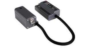

| Optical Probes | |||||||
|---|---|---|---|---|---|---|---|
| Model | Bandwidth | Inputs | Input Connector Type | Wavelength Range | Required Infiniium Baseline Software | Output Connector Type | Compatible Oscilloscopes |
| N7004A | 33 GHz | Single-mode & Multi-mode | FC/PC to 50/125 um fiber | 750 nm to 1650 nm | Version 05.70 or higher | 2.92 mm female | UXR (3.5 mm models), V, Z, Q, and 90000X |
| N7005A | 60 GHz | Single-mode | FC/PC to 9/125 um fiber | 1250 nm to 1600 nm | Version 10.25 or higher | 1.85 male | UXR (1 mm & 1.85 mm models) |
Want help or have questions?
Oscilloscope Probes – Frequently Asked Questions
What is an oscilloscope probe?
An oscilloscope probe connects an oscilloscope to a device under test (DUT). Probes then transfer the signal from the DUT to the oscilloscope for analysis, enabling you to measure and test the electrical signals.
What are the different types of oscilloscope probes?
Passive probes: These probes are the most common types, suitable for low-frequency measurements. They only contain components like resistors and capacitors that passively respond to input signals. Therefore, these probes do not require external probe power.
Active probes: These are used for high-frequency measurements. They require external probe power for the active electronic components in the probe, such as amplifiers and transistors, which are used to improve signal fidelity and performance.
Differential probes: These consist of two sensing leads that measure the differential voltage between two test points where neither lead is grounded.
Current probes: These probes measure current waveforms. There are two types — clamp-on versions that do not break the circuit or types that you connect in series with the circuit.
Can I use any probe with any oscilloscope?
Compatibility is not assured even though many probes and oscilloscopes use standard connectors. It’s critical to verify:
• Bandwidth compatibility: The probe’s bandwidth should match or exceed the oscilloscope’s bandwidth.
• Connector type: Ensure the probe’s connector matches the oscilloscope input.
• Voltage and current ratings: Confirm the probe can handle the oscilloscope’s input range.
You should refer to the specific oscilloscope and probe manuals for detailed operation and maintenance guidelines, which are crucial for effective and accurate measurements.
How do I use an oscilloscope probe?
1. Connect the probe: You must attach the probe’s connector to the oscilloscope channel input and the probe tip to the point in the circuit you want to measure.
2. Compensate the probe: Many probes have a compensation adjustment. You must connect the probe to the oscilloscope’s calibration signal and adjust the compensation until the displayed waveform is correct.
3. Set the oscilloscope: You must adjust the oscilloscope settings (e.g. time base, vertical scale) to display the signal correctly.
4. Measure: You can analyze the signal using the oscilloscope’s measurement functions.
How do I maintain my oscilloscope probe?
Regular calibration: Calibrate the probe regularly to maintain accuracy.
Proper handling: Do not bend the cables sharply; carefully handle the probe tip to prevent damage.
Cleaning: You must keep the probe tip clean for accurate measurements using appropriate cleaning solutions recommended by the probe manufacturer.
Storage: When you are not using the probes, safely store to avoid physical damage or exposure to extreme conditions.
For more detailed answers, please check out the following blog.