Tech Guide
What is RF? Understanding Radio Frequency Basics


Introduction
You’re troubleshooting a new wireless network design, and everything seems fine in simulation. But in testing, the signal strength drops unpredictably, and interference from nearby devices disrupts performance.
After hours of trial and error, you realize the issue stems from an impedance mismatch that’s causing reflections and power loss. The frustration grows as you struggle to pinpoint the problem without the advanced tools needed to diagnose it effectively.
This scenario is all too common in RF engineering. Designing and testing RF systems comes with its own set of challenges—managing signal integrity, avoiding interference, and ensuring compliance with regulatory standards. Without the right tools and expertise, these problems can lead to delays, inefficiencies, or even failed projects.
In this guide, we will explore how RF systems behave in real-world applications, the tools you need to tackle common RF problems, and practical techniques to achieve better results. By the end, you’ll have a roadmap for overcoming RF challenges and taking your designs to the next level.

RF in Practice: Beyond the Basics
RF systems rarely behave as neatly as textbook examples suggest. In real-world environments, engineers must contend with issues like signal reflections, multipath effects, electromagnetic wave interference, and frequency-dependent behavior that can impact performance.
Reflections, for instance, occur when electrical signals encounter impedance mismatches, causing portions of the original signal to bounce back and disrupt the original transmission. Similarly, multipath effects can lead to signal distortion and interference when RF waves take different paths to reach the receiver.
Understanding these challenges requires a deep focus on signal integrity, which examines how well signals maintain their intended form and strength. Mastering spectrum analysis helps engineers identify interference sources and evaluate how RF systems perform across various frequencies.
By going beyond the basics and diving into practical RF behavior, engineers can diagnose problems more effectively and design systems that perform reliably under real-world conditions.
Frequency Behavior in Real-World Systems
RF signals behave differently across frequency ranges, and understanding these differences is crucial for designing efficient systems.
At low frequencies, radio signals tend to have better penetration through obstacles, making them ideal for long-range communication systems. Mid-range frequencies balance penetration and data capacity, while high frequencies, like those used in 5G wireless networks, offer greater bandwidth but are more susceptible to attenuation and interference.
For example, a carrier signal at low frequency might excel in underground communication, while high-frequency signals are essential for applications like radar or circuit simulation testing. Using tools like Keysight’s bandwidth calculator can help engineers determine the optimal frequency for their application.
| Frequency Range | Behavior | Applications |
|---|---|---|
| Low Frequencies | Penetrates obstacles effectively | Long-range communication |
| Mid Frequencies | Balances penetration and capacity | Wi-Fi, cellular networks |
| High Frequencies | High bandwidth, low penetration | 5G, radar systems |
Impedance Mismatches and Their Impact on RF Performance
Impedance mismatches are a common challenge in RF systems, causing signal reflections that weaken transmission and increase power loss.
For instance, a poorly matched antenna can reflect power back to the transmitter, reducing efficiency and creating interference. These mismatches are closely tied to RF wavelengths, as proper impedance matching requires components and transmission lines to account for the signal's wavelength to avoid destructive interference.
To address this, you need to understand the impedance formula, basic circuit laws, and how to calculate and optimize impedance.
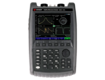
Using a network analyzer, like those from Keysight, engineers can measure impedance across various points in the system. Tools like the impedance calculator simplify the process by providing quick and accurate calculations.
Steps to Optimize Impedance Matching:
- Measure impedance: Use a network analyzer to identify mismatches.
- Adjust components: Add matching networks or adjust existing circuit elements.
- Verify results: Retest to ensure minimal signal reflection and power loss.
By addressing impedance mismatches early in the design process, engineers can significantly improve RF system performance and ensure robust operation under real-world conditions.
Regulatory Standards and Compliance
Global regulatory bodies, like the Federal Communications Commission (FCC) in the United States and the European Telecommunications Standards Institute (ETSI) in Europe, play a critical role in managing the RF spectrum.
These organizations set standards to ensure that RF systems operate within allocated frequency bands without causing harmful interference. Compliance with these standards isn’t just about following the rules; it’s essential for ensuring the reliability, safety, and legality of your designs.
Why Compliance Matters
Ignoring RF regulations can lead to costly consequences, such as fines, recalls, or denied certifications.
For example, if a product fails to meet the FCC’s emission limits, it cannot legally be sold in the U.S. Similarly, ETSI standards govern device interoperability in European markets, ensuring that products don’t interfere with other devices operating in the same spectrum.
Engineers must also consider compliance during the design phase. Regulatory requirements often dictate choices for power levels, frequency usage, and emissions.
Tools like Keysight’s spectrum analyzers are invaluable for compliance testing, helping engineers identify and mitigate potential violations early.
Key RF Standards and Their Applications
- FCC Part 15: Governs unlicensed RF devices like Wi-Fi and Bluetooth.
- ETSI EN 300 328: Covers wideband transmission systems in the 2.4 GHz band.
- ITU-R M.2083: Provides guidelines for 5G spectrum allocation.
- MIL-STD-461: Addresses RF emissions for military equipment.
Streamlining Procurement for Compliance Tools
Purchasing RF testing tools like Keysight’s spectrum analyzers through internal procurement systems can require multiple approvals. However, urgent requests often expedite the process.
For engineers needing reliable compliance tools quickly, Keysight’s buying guide simplifies the decision-making process.
By prioritizing compliance and leveraging advanced tools, engineers can avoid regulatory setbacks and deliver market-ready RF systems.
RF Power and Signal Integrity: Key Challenges in High-Frequency Systems
As RF systems operate at higher frequencies, challenges like power loss, signal integrity issues, and phase shifts become more pronounced.
Power loss increases due to phenomena like the skin effect and cable attenuation, while maintaining signal integrity requires careful attention to design and testing. Any degradation in these areas can lead to reduced system performance and reliability.
Practical solutions, such as using high-quality components and advanced testing tools, can mitigate these challenges. Keysight’s power meters and oscilloscopes are specifically designed to address these issues, helping engineers analyze RF power and maintain signal integrity.
For example, measuring RF power with a spectrum analyzer ensures that signal strength remains within the desired range.
By leveraging tools like the InfiniiVision Oscilloscope, engineers can measure and optimize RF signal quality, ensuring systems perform as intended even at high frequencies. Keysight’s refurbished equipment offers warranties and calibration services that provide both cost savings and accuracy advantages.
Power Loss in High-Frequency RF Systems
Power loss becomes a significant concern as frequency increases due to factors like the skin effect, cable attenuation, and imperfections in components.
The skin effect limits current flow to the outer surface of conductors, reducing efficiency. Similarly, attenuation in cables causes energy to dissipate as heat, further contributing to power loss.
Methods to Minimize Power Loss:
- Use low-loss cables and connectors designed for high-frequency applications.
- Optimize circuit layout to minimize resistance and parasitic effects.
- Select components rated for high-frequency performance.
Tools like Keysight’s attenuation resources and the power factor calculator simplify these calculations, helping engineers design systems with minimal energy loss.
Measuring Signal Integrity Using Oscilloscopes
Maintaining signal integrity at high frequencies requires precise measurements to detect issues like noise, distortion, and phase shifts.
Using an oscilloscope, such as Keysight’s InfiniiVision series, engineers can perform detailed analyses to identify and address these problems.
Steps to Analyze Signal Integrity:
- Connect the RF signal: Attach the signal to the oscilloscope’s input channel using a high-quality cable.
- Set frequency domain analysis: Configure the oscilloscope to display frequency domain data for detailed examination.
- Evaluate signal quality: Analyze the signal for noise levels, distortion, and phase shift.
Keysight’s oscilloscopes simplify this process, offering intuitive interfaces and advanced capabilities for accurate RF testing. By investing in premium tools, engineers can ensure their RF systems meet both performance and reliability requirements.
Advanced RF Testing Techniques for Real-World Applications
Advanced RF testing techniques, including spectrum analysis, network analysis, and time-domain measurements, are essential for ensuring system performance and diagnosing issues in real-world applications.
Spectrum analysis helps engineers identify interference and harmonics, while network analysis focuses on impedance, phase shifts, and S-parameters. Time-domain measurements are ideal for analyzing pulse signals and transient behavior.
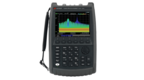
Using the right tools for these methods simplifies testing and improves accuracy. For example, a Keysight Spectrum Analyzer excels in interference detection, while network analyzers provide precise impedance matching capabilities.
| Testing Method | Purpose | Recommended Tool |
|---|---|---|
| Spectrum Analysis | Identify signal interference and harmonics | Keysight Spectrum Analyzer |
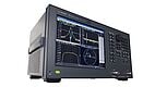
| Network Analysis | Measure impedance, phase shifts, and S-parameters | Keysight Vector Network Analyzer |
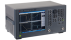
| Time-Domain Measurements | Analyze pulse signals and transient behavior | Keysight InfiniiVision Oscilloscope |
Troubleshooting RF Issues: Practical Solutions for Engineers
RF systems often face challenges like signal distortion, interference, and power fluctuations. These issues can disrupt system performance and reliability, but the right troubleshooting methods and tools can mitigate these problems effectively.
Keysight’s advanced testing tools, such as spectrum analyzers and network analyzers, are essential for diagnosing and resolving these issues.
For instance, network analyzers help engineers measure and correct impedance mismatches that cause signal distortion, while spectrum analyzers are vital for identifying interference sources and optimizing frequency selection.
Issue 1: Signal Distortion
Cause:
Signal distortion typically arises from non-linear components or impedance mismatches, which reflect signals back to their source, reducing signal quality and efficiency.
Solution:
- Use a Keysight network analyzer to measure impedance at critical points.
- Identify mismatched components and adjust their values or add matching networks.
- Verify the corrected impedance to minimize reflections and ensure a clean signal path.
Tools like Keysight’s network analyzers make these processes efficient, allowing engineers to address distortion before it impacts performance.
Issue 2: Interference from Nearby Devices
Cause:
Electromagnetic interference (EMI) from nearby devices can overlap with your RF signals, leading to poor performance and data loss.
Solution:
- Use a Keysight spectrum analyzer to identify and visualize interference sources.
- Adjust system frequencies or employ shielding to mitigate interference.
- Verify system performance under different conditions to ensure stability.
Quick Tips to Reduce RF Interference:
- Use high-quality shielding to isolate RF components.
- Maintain proper grounding and cable management.
- Design with adequate spacing between RF components and other devices.
By addressing these issues with the right tools and techniques, engineers can optimize system performance and maintain robust RF operation.

Keysight Tools for Advanced RF Testing
Keysight offers a range of tools to address these challenges, including spectrum analyzers for detecting interference, vector network analyzers for precise impedance measurements, and oscilloscopes for analyzing transient behaviors.
These tools are vital for testing and refining electronic systems, ensuring defects in circuits are minimized, and performance aligns with wireless network standards.
Advanced RF Testing Techniques: Practical Methods for Accurate Measurements
Advanced RF testing techniques are essential for addressing complex design and performance issues.
Techniques like phase noise measurements, harmonic distortion analysis, and time-domain reflectometry (TDR) enable engineers to uncover subtle issues that impact RF performance. These methods ensure precise design and robust operation, especially in high-frequency systems.
Key Techniques:
- Phase noise measurement: Evaluates frequency stability in oscillators to ensure minimal jitter.
- Harmonic distortion analysis: Identifies unwanted harmonics that degrade signal quality.
- Time-domain reflectometry (TDR): Locates faults and discontinuities in transmission lines.
Steps to Perform Advanced Measurements with Keysight Tools:
- Set up the device: Connect the DUT (Device Under Test) to the appropriate Keysight tool, such as a spectrum analyzer or network analyzer.
- Configure parameters: Adjust settings for frequency range, amplitude, or time-domain analysis as needed.
- Analyze results: Evaluate the data for phase noise, harmonic content, or signal reflections.
- Make adjustments: Use the results to refine circuit design or component selection.
Keysight’s tools simplify these processes, allowing engineers to ensure accurate performance while minimizing development time.
RF Challenges in Emerging Technologies: 5G, IoT, and Beyond
As emerging technologies like 5G, IoT, autonomous vehicles, and satellite communication push the boundaries of RF design, engineers face new challenges that demand precise testing and advanced solutions.
These technologies introduce complex requirements, such as managing high-frequency signals, ensuring energy efficiency, and mitigating interference in increasingly crowded RF environments.
Unique RF Challenges in Key Technologies:
- 5G networks: Operate at higher frequency bands (millimeter-wave) to achieve faster data rates and lower latency. This requires precise power control and beamforming to ensure reliable coverage and avoid interference.
- IoT devices: Depend on low-power RF design to maximize battery life while maintaining connectivity across diverse environments. This demands efficient signal modulation and robust interference management.
- Autonomous vehicles: Use radar systems for navigation and collision avoidance. These systems need accurate RF measurements to prevent interference and maintain system reliability.
- Satellite communication: Requires precise signal modulation and demodulation to handle high-frequency signals and ensure communication stability over long distances.
How Keysight Tools Help:
Keysight’s advanced testing solutions provide the accuracy and reliability engineers need to address these challenges:
- Vector Network Analyzers: Optimize impedance matching and measure high-frequency performance for 5G and satellite applications.
- Spectrum Analyzers: Identify interference in IoT and autonomous vehicle systems.
- Power Meters and Oscilloscopes: Ensure low-power operation and robust signal integrity in IoT devices.
By using Keysight tools, engineers can confidently navigate the complexities of emerging technologies, ensuring their designs meet performance and reliability standards.
Quick Reference Guide: Key RF Formulas for Professionals
Accurate calculations are critical for RF design and testing. This quick reference guide provides essential RF formulas to streamline your workflow and ensure reliable results during testing and troubleshooting.
Key RF Formulas:
1. Frequency Formula: f = c / λ.
Use this to calculate frequency (f) from wavelength (λ) and the speed of light (c).
Try the wavelength-to-frequency calculator.
2. Impedance Formula: Z = R + jX
Calculate total impedance (Z) using resistance (R) and reactance (jX).
3. Power Loss Formula: P = I²R
Determine power loss (P) from current (I) and resistance (R).
These formulas are essential for RF testing setups, helping engineers analyze frequency behavior, optimize impedance, and reduce power inefficiencies. For deeper insights into RF parameters, explore directivity and its importance.
Conclusion
RF design and testing come with unique challenges, from managing impedance mismatches and signal distortion to ensuring compliance with strict regulatory standards.
Emerging technologies like 5G, IoT, and autonomous vehicles only add to the complexity, requiring advanced testing techniques such as spectrum analysis, network analysis, and time-domain reflectometry.
Having a strong foundation in RF principles, combined with the right tools, empowers engineers to tackle these challenges efficiently.
Streamline your RF testing with Keysight’s premium used equipment. With industry-leading performance, warranties, and calibration services, our refurbished tools deliver top-quality results at a cost-effective price.
Explore Keysights wide variety of options to find the tools you need to elevate your RF designs and testing capabilities.
Whenever You’re Ready, Here Are
5 Ways We Can Help You
Call tech support US: +1 800 829-4444
Press #, then 2. Hours: 7am – 5pm MT, Mon– Fri
Contact our sales support team
Create an account to get price alerts and access to exclusive waitlists
Talk to your account manager about your specific needs