

Title
Voltage difference
Tech Guide
How to Measure EMF

Introduction
You're troubleshooting a sensitive analog circuit, but unexpected signal drift keeps showing up. You’ve ruled out power instability and checked your grounding. Still, the problem persists.
At this point, it’s not just about the circuit. It’s likely electromagnetic fields (EMF) are interfering with your system, and unless you measure them correctly, you're just guessing.
EMF issues aren’t limited to high-voltage labs or transmission lines. They show up in production environments, medical devices, industrial controls, and even consumer electronics. Yet, many engineers rely on assumptions or outdated tools when trying to detect or isolate EMF problems.
In this guide, you will learn how to measure EMF across different environments. We will explain the difference between electric and magnetic fields, the tools that match each use case, and the standards you need to follow for compliance.
Understanding EMF Fundamentals
Electromagnetic fields (EMF) include both electric and magnetic components, and each behaves differently based on the source, frequency, and environment. To measure EMF accurately, you need to understand how these fields interact and when to treat them separately.
Electric fields are generated by voltage differences and exist even when no current flows. Magnetic fields are produced by current flow and vary with changes in that current. In low-frequency environments, such as power systems, the electric and magnetic fields can be measured independently. In high-frequency systems, like RF applications, they merge into radiated waves.
Common EMF Sources in Electrical Systems:
- High-voltage equipment (e.g., power lines): Generates strong electric fields.
- Current-intensive devices (e.g., transformers, motors): Produce strong magnetic fields.
- Digital circuits and PCBs: Create localized near-field emissions.
- RF transmitters and antennas: Emit both electric and magnetic fields at higher frequencies.
You will often find these fields in lab setups, production environments, and compliance testing stations. In each scenario, your measurement strategy should match the field’s origin and frequency.
Electric vs. Magnetic Field Comparison
| Property | Electric Field | Magnetic Field |
|---|---|---|
| Source | Voltage difference | Current flow |
| Measured in | Volts per meter (V/m) | Amperes per meter (A/m) or Tesla (T) |
| Dominant in | High-voltage, low-current systems | Low-voltage, high-current systems |
| Frequency range | DC to GHz | DC to GHz |
| Affected by | Conductors, shielding | Loop area, conductor geometry |
| Measurement tools | Field probes, voltmeters | Magnetometers, current probes |
Property
Electric Field
Magnetic Field
Source
Title
Current flow
Current flow
Measured in
Title
Volts per meter (V/m)
Volts per meter (V/m)
Title
Amperes per meter (A/m) or Tesla (T)
Amperes per meter (A/m) or Tesla (T)
Dominant in
Title
High-voltage, low-current systems
High-voltage, low-current systems
Title
Low-voltage, high-current systems
Low-voltage, high-current systems
Frequency range
Title
DC to GHz
DC to GHz
Title
DC to GHz
DC to GHz
Affected by
Title
Conductors, shielding
Conductors, shielding
Title
Loop area, conductor geometry
Loop area, conductor geometry
Measurement tools
Title
Field probes, voltmeters
Field probes, voltmeters
Title
Magnetometers, current probes
Magnetometers, current probes
Field behavior also depends on the region—near-field or far-field—which affects whether electric or magnetic components dominate. This distinction becomes especially important in RF systems. For more on that, explore What is RF? and What is Oscilloscope Frequency?
EMF Measurement Equipment
To measure electromagnetic fields effectively, you need to choose the right instrument for your application, whether you're tracing interference in a PCB, validating shielding in a power cabinet, or performing compliance testing.
Tools for EMF measurement range from basic handheld meters to high-end lab-grade instruments. Each tool offers different levels of sensitivity, frequency coverage, and analysis depth.
Basic EMF meters help with general field strength assessments. For more complex diagnostics or frequency-specific analysis, engineers turn to spectrum analyzers and oscilloscopes. When measuring magnetic fields in particular, magnetometers are essential for capturing accurate, directional data.
Engineers often assume they need to buy brand-new instruments to get reliable results, but many find premium used equipment offers the same performance, backed by calibration and warranty support. As Erica, a Keysight account manager, notes: “Customers come to us and buy used because they get premium KS quality, with a lower price, and we ship within 2 weeks.”
Basic EMF Meters
Basic EMF meters are often the first choice for quick diagnostics or field surveys. These meters come in single-axis or three-axis models:
- Single-axis meters measure one spatial dimension at a time, requiring manual rotation to find peak field strength.
- Three-axis meters measure all three spatial dimensions simultaneously, offering faster and more accurate readings.
When choosing an EMF meter, consider the following features:
- Frequency range (e.g., 50 Hz to several kHz or MHz)
- Axis type (single vs. tri-axis)
- Display resolution and update rate
- Measurement range (field strength limits)
- Data logging or export capabilities
- Built-in filters or averaging functions
- Battery life and ruggedness for field use
While limited in spectral resolution, these meters provide an essential baseline for exposure assessments or troubleshooting noisy environments. For basic voltage or current measurements that may relate to EMF sources, a digital multimeter can offer complementary insight.
Spectrum Analyzers
To analyze EMF in the frequency domain, especially when characterizing RF interference or emissions, spectrum analyzers provide precise visibility across a wide bandwidth. These tools use external antennas and probes to detect radiated signals and display power versus frequency.
Use cases include:
- Measuring EMI in electronics enclosures
- Identifying specific frequency sources
- Troubleshooting wireless interference
Engineers can explore Keysight’s Spectrum Analyzer Buying Guide or learn how a spectrum analyzer works for a more technical background.
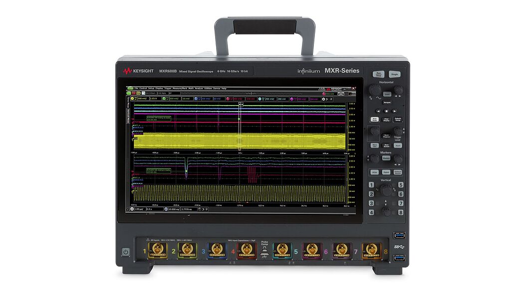
Oscilloscopes for EMF Analysis
Oscilloscopes are ideal for time-domain analysis of EMF signals, particularly transient events or pulsed fields. With the right probes and coupling settings, scopes can capture voltage spikes or current surges tied to EMF sources.
To get the most from an oscilloscope in this role:
- Use appropriate coupling (AC/DC) and bandwidth settings
- Connect probes with proper shielding and grounding
- Set triggering to capture intermittent events
For equipment tips, visit the Used Oscilloscope Buying Guide, and review oscilloscope coupling basics to ensure accurate field capture.
Measurement Methodologies and Standards
Accurate EMF measurement depends on standardized methods that ensure consistency, repeatability, and regulatory compliance. Whether you're conducting lab testing or field assessments, aligning with established EMF testing standards helps you meet exposure limits, validate shielding effectiveness, and avoid costly rework.
Two major standards guide EMF measurement practices worldwide: IEEE 644 and IEC 61786. Each offers specific recommendations for measurement protocols, probe placement, calibration, and data interpretation. Depending on your industry and location, you may also need to meet additional requirements for workplace safety, product certification, or environmental assessments.
IEEE Standards for EMF Measurement
The IEEE Std 644 is widely adopted in North America and focuses on measuring power-frequency magnetic and electric fields (typically 50/60 Hz) in controlled environments. It provides detailed guidance on instrumentation, spatial averaging, and test setups to ensure consistency across labs and systems.
Key steps in the IEEE 644 process include:
- Define the test objective (e.g., exposure assessment or product validation)
- Choose appropriate instrumentation with calibrated probes
- Establish a test grid with fixed measurement points
- Measure field strengths at standardized heights and distances
- Apply spatial averaging if required
- Document environmental conditions
- Compare results to regulatory or internal benchmarks
This standard is especially relevant for testing near power lines, electrical panels, and industrial equipment where low-frequency magnetic fields dominate.
IEC Standards
IEC 61786 and its updated versions serve as the international counterpart to IEEE 644 but with a broader scope. While IEEE 644 is primarily focused on measuring low-frequency magnetic fields near overhead power lines and large utility equipment, IEC 61786 is designed for in-situ measurements of both electric and magnetic fields in residential, commercial, and industrial environments.
Compared to IEEE, the IEC standard places more emphasis on:
- Instrument calibration traceability
- Probe isotropy and uncertainty estimation
- Field mapping in real-world environments (e.g., offices, factories)
While IEEE standards lean toward structured lab conditions, IEC 61786 supports in-situ field testing across diverse operating environments, making it essential for international certification and consumer safety.
Industry-Specific Requirements
Different industries apply tailored EMF testing standards based on use cases and risk levels:
- Telecom: Must meet ITU-T and IEC standards for device emissions and safe exposure limits.
- Energy: Utilities follow IEEE/IEC guidelines for substation and transmission line fields.
- Manufacturing: Industrial automation systems often require local or sector-specific EMF compliance for worker safety and equipment immunity.
Practical EMF Measurement Techniques
Field conditions rarely match ideal lab setups, which makes real-world EMF testing more complex but also more critical. Whether you're validating shielding effectiveness, identifying emissions from power devices, or mapping exposure zones, you need to apply the right measurement strategy for your environment and objective.
The key to effective EMF testing lies in correct probe placement, understanding field decay, choosing appropriate measurement frequency ranges, and knowing the difference between near-field and far-field behaviors.
Electric Field Measurement
When measuring electric fields, probe placement and grounding have a significant effect on accuracy. Use non-conductive mounts and ensure the probe’s ground plane is properly referenced to reduce error. Electric fields decrease rapidly with distance, so always define your test distance clearly, especially in compliance evaluations.
Electric Field Strength by Distance (V/m)
| Distance from Source | Approximate Field Strength |
|---|---|
| 5 cm | 1000 V/m |
| 10 cm | 250 V/m |
| 20 cm | 60 V/m |
| 50 cm | 10 V/m |
Distance from Source
Approximate Field Strength
5 cm
Title
1000 V/m
1000 V/m
10 cm
Title
250 V/m
250 V/m
20 cm
Title
60 V/m
60 V/m
50 cm
Title
10 V/m
10 V/m
These values are arbitrary but emphasize the variation depending on source distance, geometry, shielding, and frequency. A field that measures high at 10 cm may be negligible at 50 cm, so capturing distance is essential for reporting.
To ensure your test bandwidth aligns with the signal content, reference the oscilloscope bandwidth guide. An undersized bandwidth filter can underreport peak field activity or miss brief transients entirely.
Magnetic Field Measurement
Magnetic field testing often requires measuring both AC and DC components, particularly in environments like transformer stations, EV chargers, or manufacturing equipment. Use current probes or magnetometers with high sensitivity, and align the sensor based on the expected direction of the field lines.
Common magnetic field measurement mistakes to avoid:
- Incorrect probe orientation
- Neglecting low-frequency content in AC fields
- Using improper shielding in high-noise environments
- Overlooking DC bias fields in power converters
- Failing to calibrate probes at operating frequencies
- Ignoring field gradients near complex geometries
Magnetic field behavior is also closely tied to impedance characteristics, so reviewing this comprehensive impedance formula guide can help in modeling how conductors and loads influence your results.
Broadband vs. Frequency-Specific Measurements
Some applications call for broadband measurements, which give a full-picture snapshot of field strength across a wide range. These are useful for quick surveys, exposure assessments, or locating strong sources of interference.
Other times, you'll need frequency-specific measurements to isolate emissions from switching power supplies, RF modules, or harmonic distortions. In those cases, you’ll use tools like spectrum analyzers or tuned antennas to isolate narrow bands.
Choose frequency-specific analysis when:
- You need to identify the source of interference
- You are performing emissions compliance testing
- Narrowband communication systems are affected
Use broadband analysis when:
- You are surveying unknown environments
- You need to capture total exposure levels quickly
To better understand how bandwidth influences both measurement resolution and accuracy, see this bandwidth formula reference.
Near-Field vs. Far-Field Considerations
The distinction between near-field and far-field plays a major role in both test strategy and equipment choice.
The near-field region exists close to the EMF source (typically within λ/2π), where electric and magnetic fields are decoupled and behave independently. The far-field region is where electric and magnetic components combine into radiated waves, and radiation levels become the primary measurement concern, especially for compliance with RF safety standards or broadcast emissions.
In the near-field:
- Measure electric and magnetic fields separately
- Use small, localized probes
- Expect field strength to decay rapidly with distance
In the far-field:
- Use antennas and directional sensors
- Expect wave impedance to stabilize (377 ohms in free space)
- Fields propagate uniformly, with predictable drop-off
Transitioning between these zones can create confusing data unless you account for the change in field behavior. If you are measuring antenna emissions or testing wireless product range, review this guide on how to measure antenna gain with a network analyzer, a useful resource for understanding field propagation and directionality.
Data Collection and Analysis
Collecting and analyzing EMF data goes beyond taking a few readings and logging them in a spreadsheet.
To produce reliable and actionable results, you need to plan your measurements carefully, apply consistent recording practices, and use statistical methods to interpret what the data is really telling you.
Whether you're testing for compliance, validating shielding, or identifying interference sources, this section will help you turn raw data into clear insights.
Measurement Planning
Before you start taking readings, develop a structured plan that defines where, when, and how measurements will be taken. This ensures repeatability and reduces the chance of missing key data points due to environmental variation or inconsistent technique.
Follow these steps to plan your EMF survey:
- Define the test objective (e.g., exposure compliance, interference mapping)
- Determine the area of interest and break it into a measurement grid
- Set measurement height and orientation (e.g., 1 meter above ground, probe vertical)
- Plan timing to reduce environmental noise (avoid heavy machinery hours, for instance)
- Label all measurement points clearly
- Verify all equipment calibration and battery levels
- Document environmental conditions (temperature, nearby equipment, etc.)
This approach helps you collect data that’s easy to interpret and compare, even across different test sessions or team members.
Data Recording Protocols
Accurate data logging ensures consistency, traceability, and usefulness of your measurements. Use digital logging tools when possible, and make sure each entry includes:
- Measurement point ID
- Date and time
- Instrument and probe used
- Frequency or bandwidth settings
- Field strength values
- Environmental notes (e.g., nearby noise sources)
Processing raw data often requires filtering and signal extraction, where digital signal processing becomes critical. It allows you to clean up your dataset and isolate meaningful trends.
Statistical Analysis of EMF Data
Once collected, EMF data should be analyzed using statistical techniques that reflect how fields vary over time and space. You can average readings, compute peak values, or apply weighting factors depending on the application.
| Analysis Method | Use Case | Notes |
|---|---|---|
| Time averaging | Long-term exposure assessment | Use RMS or mean values over time |
| Spatial averaging | Workplace safety evaluations | Required in some compliance standards |
| Peak detection | Interference and emissions analysis | Captures worst-case transients |
| Weighted averaging | Human exposure modeling | Applies correction factors |
Analysis Method
Use Case
Notes
Time averaging
Title
Long-term exposure assessment
Long-term exposure assessment
Title
Use RMS or mean values over time
Use RMS or mean values over time
Spatial averaging
Title
Workplace safety evaluations
Workplace safety evaluations
Title
Required in some compliance standards
Required in some compliance standards
Peak detection
Title
Interference and emissions analysis
Interference and emissions analysis
Title
Captures worst-case transients
Captures worst-case transients
Weighted averaging
Title
Human exposure modeling
Human exposure modeling
Title
Applies correction factors
Applies correction factors
These techniques help reduce uncertainty and improve confidence in your results, particularly when testing in variable environments.
Software Tools for EMF Analysis
Today’s EMF measurement tools often include or integrate with software that helps you visualize, analyze, and report on field strength data. These platforms support:
- 2D/3D field mapping
- Time-series waveform visualization
- Statistical trend analysis
- Report generation with built-in templates
For waveform-based measurements, understanding how an oscilloscope waveform represents EMF behavior can improve how you interpret time-domain data. Combined with software tools, this gives you a full picture, from collection to final reporting.
EMF Measurement in Specific Applications
The methods and tools you use to measure EMF can vary significantly depending on the application. Power systems, consumer electronics, and workplace environments all present different challenges and compliance requirements. Adapting your approach to each setting ensures accurate data and meaningful results.
Power Transmission Systems
High-voltage substations and transmission lines generate strong magnetic fields, particularly at 50/60 Hz. Testing in these environments focuses on evaluating exposure levels, field containment, and equipment immunity.
Protocols typically involve:
- Measuring magnetic field strength at various distances from transformers, switchgear, and lines
- Monitoring long-term exposure using time-averaged measurements
- Verifying field attenuation across barriers or enclosures
Safety precautions:
- Use insulated tripods and probes with proper dielectric strength
- Maintain minimum approach distances (as defined by OSHA or equivalent standards)
- Avoid testing during peak load periods unless required
- Confirm grounding integrity before setting up instruments
- Always wear arc-rated PPE and follow site-specific lockout/tagout procedures
When evaluating the impact of EMF on power systems or testing immunity, tools like DC power supplies may also be used for controlled signal injection or reference voltage during calibration.
Electronic Device Emissions
In circuit design and product development, EMF testing is essential for identifying unintended emissions from electrical devices, PCBs, and enclosures. These emissions can impact performance, violate regulatory limits, or interfere with nearby systems.
To measure emissions accurately:
- Use near-field probes to scan PCB traces, ICs, and interconnects
- Employ shielding tents or chambers to isolate test environments
- Measure at multiple orientations and points around the device
- Capture both radiated and conducted emissions across relevant frequency ranges
Signal fidelity is especially important here. Poor signal integrity can lead to false readings or misinterpretation of EMF behavior, particularly at high data rates or edge transitions.
Workplace EMF Assessment
Workplace EMF assessments help ensure environments comply with occupational exposure limits. These assessments usually follow a structured sampling plan.
Steps include:
- Define the grid layout around workstations or machinery
- Measure at employee height (typically 1 m) at each point
- Record readings during normal operating conditions
- Apply time and spatial averaging where applicable
- Compare findings to national exposure limits (e.g., ICNIRP, IEEE C95.1)
Advanced EMF Measurement Techniques
Basic EMF surveys provide field strength data. For deeper insights, advanced testing workflows are better suited to troubleshooting interference, validating designs, or evaluating mitigation strategies.
These techniques often involve more sophisticated tools and structured methodologies, helping engineers capture spatial field behavior, quantify shielding performance, and visualize EMF hotspots in real-world environments.
Shielding Effectiveness Measurement
To confirm that shielding is working as intended, you need to measure EMF levels before and after installation, using the same location, orientation, and test setup for accurate comparison.
Steps to measure shielding effectiveness:
- Measure baseline EMF levels without shielding.
- Install shielding material (enclosure, cable wrap, coating, etc.).
- Repeat measurements using the same instrument, probe orientation, and distance.
- Calculate attenuation using the formula:
SE (dB) = 20 × log₁₀ (Unshielded / Shielded)
5. Document results including environmental conditions and measurement frequency.
Quantifying performance this way helps validate product compliance and avoid under- or over-engineering the shield.
EMF Imaging and Mapping
Visualizing field strength across a defined area allows you to identify hotspots, leakage paths, or zones of poor shielding. EMF mapping uses high-resolution scans to generate 2D or 3D heatmaps of field intensity, helping assess exposure or emissions across a system or workspace.
To create an EMF map:
- Use a scanning platform or manually grid a test surface
- Mount a tri-axial probe or near-field sensor on a movable arm or XYZ gantry
- Collect data at fixed intervals (e.g., every 2 cm)
- Use mapping software to convert data into a visual overlay
For frequency-selective maps, spectrum analysis tools provide powerful insights by combining spatial and spectral data in a single scan.
Interpreting and Reporting EMF Measurements
Accurate measurement is only the first step, translating that data into meaningful insights and actionable reports is just as important.
Whether you are performing internal diagnostics, third-party testing, or compliance validation, your report should clearly show how field strengths compare to defined limits and document any uncertainties that could affect results.
Structured interpretation ensures that your findings hold up under review and support informed decisions.
Comparing Results to Standards
Once you have collected EMF data, benchmark it against relevant exposure or emissions limits such as those from IEEE C95.1, ICNIRP, FCC, or industry-specific standards. Use peak, average, or RMS values as required by the testing protocol, and always apply correction factors for probe response and environmental variation.
Creating Comprehensive Reports
An effective EMF report should include:
- Test objective and scope
- Description of the environment and equipment
- Instrument specifications and calibration info
- Grid layout, probe orientation, and height
- Data tables and annotated field maps
- Comparison to applicable standards
- Uncertainty estimates and methodology
- Observations or anomalies
Be transparent about measurement uncertainty. Use statistical tools or reference values to indicate your confidence range, and display these visually where possible.
Common Interpretation Pitfalls
Engineers often misinterpret EMF data due to:
- Failing to account for measurement distance
- Misusing frequency-weighted averages
- Ignoring the effect of probe orientation
- Overlooking environmental influences (e.g., metal structures)
- Confusing peak vs. RMS values in reporting
- Comparing results to incorrect or outdated standards
Avoiding these mistakes ensures your conclusions are defensible, accurate, and applicable across diverse engineering or regulatory contexts.
Troubleshooting EMF Measurement Issues
Even with the right tools and setup, EMF measurements can be skewed by environmental noise, equipment drift, or operator error. Troubleshooting these issues ensures your data remains reliable, especially when results support compliance claims or design decisions.
This section outlines how to verify your instruments, manage environmental interference, and account for uncertainty in your results.
Equipment Calibration and Verification
Regular calibration is essential for maintaining accuracy, especially when working across wide frequency ranges or small signal levels. For most EMF instruments, annual calibration is standard, but you should verify performance before each critical test session.
Basic steps include:
- Check the manufacturer’s calibration interval
- Run self-tests or internal diagnostics where available
- Use a known reference source (e.g., calibrated signal generator) to verify response
- Inspect probes and cables for damage or drift
- Log verification results before and after testing
Environmental Interferences
Common sources of ambient interference include fluorescent lighting, nearby electronics, HVAC motors, and radio towers. To reduce noise:
- Test during off-peak hours
- Use shielding enclosures or ferrite clamps
- Relocate sensitive instruments away from high-noise areas
Measurement Uncertainties
Always quantify and report uncertainty using published methods. Include:
- Instrument accuracy specs
- Probe placement tolerance
- Environmental variability
- Averaging or processing errors
Document uncertainty as ±X% or ±Y dB and include it in your final report to support data transparency.
Invest in Precision with Keysight’s Certified Pre-Calibrated Equipment
Conclusion
Measuring EMF accurately requires the right tools, tested methodologies, and a clear understanding of how electric and magnetic fields behave in different environments.
From planning your measurement grid to interpreting results and maintaining your gear, every step impacts the quality and reliability of your data. Whether you are troubleshooting, designing, or validating for compliance, applying these best practices ensures confident decision-making.
Need high-performance tools without stretching your budget? Explore Keysight’s premium Used Equipment, professionally inspected, calibrated, and ready to ship. Get the performance your EMF testing demands at a fraction of the cost.
Whenever You’re Ready, Here Are
5 Ways We Can Help You
1
2
Call tech support US: +1 800 829-4444
Press #, then 2. Hours: 7am – 5pm MT, Mon– Fri
3
Contact our sales support team
4
Create an account to get price alerts and access to exclusive waitlists
5
Talk to your account manager about your specific needs