- Introduction
- The Resonant Frequency Formula
- Key Components and Their Impact
- Examples of Resonant Frequency Calculations
- 3 Common Challenges Engineers Face with Resonant Frequency
- Common Problems in Applying the Formula
- How to Troubleshoot Resonant Frequency Errors
- Common Resonance Errors and Their Solutions
- Additional Diagnostic Tools and Techniques
- Tools for Accurate Resonant Frequency Measurement
- Key Features to Look for in Tools
- Real-World Applications of the Resonant Frequency Formula
- Practical Applications in Circuit Design
- Overcoming Common Roadblocks in Frequency Calculations
- Common Roadblocks and How to Overcome Them
- Solutions and Tips for Overcoming Roadblocks
- How to Optimize Your Designs Using the Resonant Frequency Formula
- Key Optimization Strategies
- Future Trends in Resonant Frequency Measurement
- Advancements in Measurement Technology
- Emerging Materials and Components Impacting Resonance
- Invest in Precision with Keysight’s Certified Pre-Calibrated Equipment
- Conclusion
- Whenever You’re Ready, Here Are 5 Ways We Can Help You
Many engineers run into the same frustration when working with circuits—unexpected frequency shifts that throw off performance.
You double-check your calculations, but something still doesn’t add up. The circuit should resonate at a specific frequency, yet measurements show a slight but critical deviation. What went wrong?
Resonant frequency plays a crucial role in circuit design, affecting everything from signal integrity to power efficiency. Whether you're designing filters, oscillators, or RF systems, even small miscalculations or component variations can lead to costly performance issues.
Understanding how to apply the resonant frequency formula accurately and knowing how to troubleshoot deviations can make a huge difference in optimizing circuit behavior.
In this article, we break down the resonant frequency formula, highlight common challenges engineers face when applying it, and explore the best tools for accurate measurement. Along the way, we will provide practical solutions to ensure your designs perform as expected.
The Resonant Frequency Formula
At the heart of many circuit designs lies the concept of resonant frequency; the frequency at which a system naturally oscillates with maximum amplitude.
In electrical engineering, this occurs in RLC circuits (resistor-inductor-capacitor circuits), where the combination of inductance (L) and capacitance (C) determines the resonant frequency.
The standard formula for calculating resonant frequency in an ideal RLC circuit is:
fr = 1 / (2π√(LC))
where:
- fr = resonant frequency in hertz (Hz)
- L = inductance in henries (H)
- C = capacitance in farads (F)
At this frequency, the inductive reactance (XL) and capacitive reactance (XC) cancel each other out, minimizing impedance and allowing maximum current flow. This principle plays a critical role in circuit behavior, influencing the efficiency and performance of filters, oscillators, and tuned circuits.
For example, in band-pass filters, engineers use resonance to allow only a specific frequency range to pass while blocking others. Similarly, oscillators rely on precise resonant frequency calculations to generate stable waveforms for communication systems.
Understanding how to apply this formula ensures accurate frequency selection and performance tuning in real-world applications.
Key Components and Their Impact
To fully grasp resonant frequency, it's essential to understand the roles of inductance, capacitance, and resonance in circuit behavior.
Inductance (L)
Inductance measures a coil’s ability to store energy in a magnetic field when current flows through it. It directly affects reactance, which varies with frequency:
XL = 2πfL
At higher frequencies, inductors resist current flow more. In resonance, the inductor's reactance cancels out the capacitor's reactance, allowing efficient energy transfer.
Capacitance (C)
Capacitors store electrical charge and influence how circuits respond to alternating signals. Their reactance is given by:
XC = 1 / (2πfC)
At low frequencies, capacitors block current, but at higher frequencies, they allow more current to pass. At resonance, the capacitive reactance matches the inductive reactance.
Resonance
Resonance occurs when \(X_L = X_C\), minimizing overall impedance in an RLC circuit. This is why resonant circuits are used in filters, antennas, and oscillators. They allow signals at a specific frequency to pass while attenuating others. Engineers rely on impedance analyzers to measure resonance accurately. This impedance calculator can help.
Examples of Resonant Frequency Calculations
| Inductance (L) | Capacitance (C) | Resonant Frequency (fr) |
| 10 µH | 100 pF | 5.03 MHz |
| 1 mH | 10 nF | 50.3 kHz |
| 50 µH | 1 µF | 56.4 kHz |
Accurate frequency calculations are crucial in high-frequency applications such as RF design and power electronics. Using reliable tools for measurement ensures precision, saving time and reducing design errors.
3 Common Challenges Engineers Face with Resonant Frequency
Even with a solid understanding of the resonant frequency formula, engineers often encounter real-world challenges that complicate their calculations and measurements.
These issues can lead to inaccurate frequency estimations, unexpected circuit behavior, and costly design errors. Below are three of the most common challenges and their impact on circuit design.
1. Non-Ideal Conditions in Real-World Circuits
In theory, resonance occurs when inductive and capacitive reactances cancel each other out, but real-world circuits introduce parasitic elements, resistive losses, and component tolerances that alter expected behavior.
These factors cause shifts in the resonant frequency, impacting performance in applications like RF circuits and power electronics.
- Parasitic inductance and capacitance from PCB traces and component leads can slightly shift resonance, making precise calculations difficult.
- Resistive losses in inductors and capacitors affect the quality factor (Q) of a circuit, reducing efficiency.
- Component tolerances can introduce small variations in L and C values, leading to unexpected frequency deviations.
Learn more about circuit loading and its impact on resonance.
2. Inaccurate Results Due to Measurement and Calculation Errors
Accurate resonant frequency measurements depend on correct component values and proper testing techniques. Engineers often run into issues such as:
- Incorrect component values due to manufacturing tolerances or substitution of similar-rated components.
- Miscalculations when manually computing resonant frequency, especially when working with high-frequency circuits.
- Faulty measurement tools that introduce additional error, particularly when working with small capacitance or inductance values.
Small errors can lead to frequency mismatches, causing filters to reject the wrong frequencies or oscillators to drift. Using high-precision measurement tools can help engineers avoid these issues.
3. Tool Limitations and Bandwidth Constraints
Not all testing equipment can handle high-frequency circuits with the accuracy engineers require. Some common limitations include:
- Bandwidth restrictions in oscilloscopes and analyzers, which prevent accurate measurement of high-frequency signals.
- Low-resolution measurements in standard multimeters or budget analyzers, leading to unreliable data.
- Impedance mismatches between the circuit and measurement device, distorting test results.
Understanding bandwidth limits is crucial for selecting the right tools for resonant frequency analysis.
Common Problems in Applying the Formula
Even when using the correct resonant frequency equation, engineers face practical issues that can affect accuracy.
- Component tolerance: Small variations in L and C values can significantly impact frequency calculations, especially in high-Q circuits.
- Environmental factors: Temperature changes, humidity, and aging components can shift the resonant frequency over time.
- Tool precision: Budget instruments may lack the resolution needed to measure frequency shifts in sensitive applications.
By accounting for these challenges and selecting reliable measurement tools, engineers can improve circuit performance and ensure accurate frequency control.
How to Troubleshoot Resonant Frequency Errors
Even small deviations in resonant frequency can disrupt circuit performance, leading to inefficiencies or malfunctions.
If your frequency measurements are off, the issue could stem from incorrect component values, miscalculations, or limitations in testing tools. Below are troubleshooting techniques to help engineers diagnose and correct resonance-related errors.
Check this guide on measuring amplitude for better measurement accuracy, and learn how signal averaging can improve test results.
Common Resonance Errors and Their Solutions
The table below outlines some of the most frequent issues engineers encounter when measuring resonant frequency, along with practical solutions:
| Error | Solution |
|---|---|
| Frequency Shift Due to Temperature Variations | Use components with a lower temperature coefficient and design circuits with temperature compensation. |
| Measurement Inaccuracy Due to Tool Limitations | Upgrade to high-precision analyzers and oscilloscopes for more reliable frequency readings. |
| Parasitic Elements Affecting Frequency | Use shielding, optimize PCB layout, and minimize lead lengths to reduce parasitic inductance and capacitance. |
| Component Tolerance Causing Variations | Choose high-precision components with tighter tolerances to reduce frequency shifts. |
| Signal Noise Interfering with Readings | Apply signal averaging techniques and use low-noise measurement setups to improve accuracy. |
Additional Diagnostic Tools and Techniques
To pinpoint and resolve resonance-related errors, engineers can leverage the following high-precision diagnostic tools:
- Vector Network Analyzers (VNAs): Measure impedance and analyze resonant frequency behavior in RF circuits.
- Impedance Analyzers: Provide detailed insights into how inductance and capacitance affect circuit resonance.
- High-Precision Oscilloscopes: Allow for real-time frequency analysis and troubleshooting of unexpected frequency shifts.
By using the right tools and refining measurement techniques, engineers can ensure accurate resonant frequency calculations and optimize circuit performance.
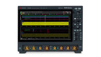
Tools for Accurate Resonant Frequency Measurement
Accurate resonant frequency measurement is critical in circuit design, ensuring proper filter performance, stable oscillators, and efficient RF systems.
Selecting the right measurement tools can mean the difference between a well-optimized circuit and one plagued by unexpected frequency shifts. High-quality tools, such as analyzers and oscilloscopes from Keysight, offer the precision and reliability needed to measure resonant frequencies accurately.
Engineers working with high-frequency circuits or sensitive analog designs benefit from using professional-grade instruments designed to minimize error, provide real-time feedback, and handle complex frequency analysis.
Why Use Professional-Grade Measurement Tools?
The right tools simplify resonant frequency measurements and reduce errors caused by instrument limitations. Keysight’s instruments, for example, are trusted for their:
- Wide frequency range: Capable of handling high-frequency signals with accuracy.
- Precision and calibration: Minimize measurement errors with highly accurate and factory-calibrated equipment.
- Advanced features: Automated frequency sweeps, impedance analysis, and real-time spectrum monitoring help engineers optimize circuits efficiently.
Learn more about spectrum analyzers and their role in frequency analysis. If impedance is a key factor in your design, a network analyzer is often the best tool. Compare network analyzers and oscilloscopes here.
Key Features to Look for in Tools
When selecting tools for resonant frequency analysis, engineers should prioritize the following features:
- High measurement resolution: Ensures small frequency shifts are accurately detected.
- Real-time performance analysis: Provides live feedback while making circuit adjustments.
- Temperature compensation: Reduces errors caused by environmental variations.
Choosing precision tools with these capabilities can significantly improve measurement reliability, ensuring that resonant frequencies are measured and optimized with confidence. Compare different measurement tool options to determine the best fit for your application.
Real-World Applications of the Resonant Frequency Formula
Resonant frequency plays a vital role in designing and optimizing electronic circuits. Engineers rely on precise frequency calculations to ensure components like filters, oscillators, and RF systems perform as expected. A miscalculation in resonance can lead to signal loss, distortion, or inefficient power transfer.
By applying the resonant frequency formula, you can fine-tune circuit behavior, enabling optimal performance in signal processing, wireless communication, and power electronics. Whether designing a band-pass filter for audio processing or an oscillator for a stable clock signal, accurate frequency calculations are essential. Learn how cutoff frequency matters in filter design.
Practical Applications in Circuit Design
Filters
Filters control which frequencies pass through a circuit and which are attenuated.The resonant frequency formula is used to design:
- Low-pass filters: Allow frequencies below the resonance point while blocking higher ones.
- High-pass filters: Block low frequencies and allow higher ones to pass.
- Band-pass filters: Permit only a specific frequency range while rejecting others.
- Band-stop filters (notch filters): Block a particular frequency range, useful for eliminating unwanted interference.
Accurate frequency calculation ensures filters operate at the correct cutoff frequency, improving performance in audio processing, RF communication, and instrumentation.
Oscillators
Oscillators generate stable waveforms for timing circuits, signal generation, and clock synchronization. Resonant frequency determines their output frequency, impacting the stability and accuracy of signals in:
- Crystal oscillators for microcontrollers and processors.
- LC oscillators for RF applications.
- Voltage-controlled oscillators (VCOs) for frequency modulation and synthesizers.
Designing oscillators with precise resonant frequencies ensures low phase noise and stable operation.
RF Circuit Design
In radio-frequency (RF) and wireless communication, accurate resonance calculations are critical for:
- Antenna tuning: Ensuring antennas resonate at the correct frequency for efficient signal transmission.
- Impedance matching: Minimizing signal reflection in transmission lines.
- Resonant cavity filters: Used in radar and satellite communication to isolate specific frequencies.
Accurate resonant frequency measurements in RF design lead to better signal clarity, reduced interference, and improved system efficiency.
By leveraging high-precision measurement tools, engineers can fine-tune resonance-based circuits, improving the reliability and efficiency of their designs.
Overcoming Common Roadblocks in Frequency Calculations
Accurately calculating resonant frequency is essential for designing efficient circuits. However, you may face technical limitations, component inconsistencies, and measurement challenges that slow down project timelines and impact circuit performance.
Small miscalculations can lead to unstable oscillators, ineffective filters, and inefficient RF systems. By identifying these roadblocks early and applying effective solutions, you can improve accuracy and optimize your designs.
Evaluating calibration companies ensures that measurement tools provide reliable results, while understanding calibration certificates helps validate instrument accuracy.
Common Roadblocks and How to Overcome Them
| Roadblock | Impact on Frequency Calculations |
|---|---|
| Lack of advanced tools | Engineers struggle to measure inductance and capacitance precisely, leading to inaccurate resonant frequency calculations. |
| Inconsistent component quality | Variations in inductor and capacitor values result in frequency shifts that can disrupt circuit performance. |
| Limited knowledge of advanced techniques | Engineers may not utilize modern simulation software to predict and adjust resonant behavior before physical testing. |
Solutions and Tips for Overcoming Roadblocks
| Solution | How It Helps |
|---|---|
| Invest in quality equipment | Ensures precise, high-accuracy frequency measurements, reducing design errors. |
| Use simulation tools | Helps engineers model resonant circuits and anticipate performance issues before physical implementation. |
| Calibrate instruments regularly | Prevents inaccuracies caused by equipment drift over time, maintaining measurement reliability. |
By combining high-quality tools, accurate calibration, and simulation techniques, engineers can significantly improve the accuracy of resonant frequency calculations and ensure the stability of their designs.
How to Optimize Your Designs Using the Resonant Frequency Formula
Accurate resonant frequency calculations can make or break a circuit’s performance. Whether designing filters, oscillators, or RF circuits, optimizing resonance ensures better signal integrity, efficiency, and stability.
By fine-tuning component values, avoiding common errors, and leveraging high-precision measurement tools, engineers can significantly improve their designs.
Understanding frequency domain analysis can also help engineers detect and correct signal issues. Learn more about FFT (Fast Fourier Transform) and how aliasing impacts frequency measurements.
Key Optimization Strategies
Fine-tuning component values
- Small adjustments in inductance (L) and capacitance (C) can bring a circuit closer to its ideal resonant frequency.
- Selecting high-precision components with tight tolerances minimizes frequency drift.
- Using trimmer capacitors or adjustable inductors allows for real-time tuning.
Mitigating errors
- Double-check resonant frequency calculations and verify against simulation models.
- Reduce parasitic inductance and capacitance in PCB layouts by keeping traces short and using proper grounding techniques.
- Avoid aliasing issues when analyzing frequency response with oscilloscopes or spectrum analyzers.
Leveraging high-precision tools
- Use high-resolution frequency analyzers to detect small deviations.
- Implement vector network analyzers (VNAs) and impedance analyzers for accurate impedance matching and tuning.
- Regularly calibrate instruments to maintain measurement accuracy.
By following these optimization techniques, you can ensure greater accuracy, stability, and efficiency in resonant frequency-dependent circuits.
Future Trends in Resonant Frequency Measurement
As electronic designs push toward higher frequencies and greater precision, resonant frequency measurement continues to evolve.
Advances in measurement tools, AI-driven analysis, and emerging materials are transforming how engineers fine-tune circuits for optimal performance. These innovations improve accuracy, reduce testing time, and minimize design errors.
Next-generation measurement techniques, such as digital signal processing (DSP) and high-speed analog-to-digital converters (ADCs), are making frequency analysis more precise than ever. Learn how digital signal processing enhances measurement techniques and why analog-to-digital converters are essential for modern resonant frequency testing.
Advancements in Measurement Technology
Modern tools are improving how engineers measure and analyze resonant frequencies. Innovations in AI, machine learning, and automated testing are making frequency measurement faster and more reliable.
- AI-driven measurement tools: Advanced analyzers now incorporate AI algorithms to detect patterns, reduce noise, and predict component failures based on frequency response.
- Automated testing and real-time feedback: High-precision instruments provide immediate results, allowing engineers to make real-time adjustments to circuit designs.
- High-speed ADCs and DSP techniques: Faster sampling rates and enhanced digital processing improve the accuracy of frequency response measurements.
These advancements help engineers reduce design iterations, improve efficiency, and achieve more precise resonant frequency measurements in RF, power electronics, and communication systems.
Emerging Materials and Components Impacting Resonance
New materials are reshaping how inductors, capacitors, and circuit components behave at high frequencies. These innovations improve component tolerances, thermal stability, and miniaturization for advanced electronic applications.
- Graphene-based capacitors: Offer higher capacitance with minimal losses, improving high-frequency performance.
- Advanced ceramics: Used in high-Q capacitors to reduce losses and improve resonance stability.
- Nanomaterial inductors: Provide compact designs with lower parasitic losses, improving impedance matching in RF circuits.
- Flexible electronic substrates: Enable high-frequency applications in wearable tech, automotive radar, and 5G networks.
By leveraging these emerging materials, engineers can achieve tighter tolerance control, improve thermal stability, and optimize circuit performance at higher frequencies.
The future of resonant frequency measurement is driven by smarter tools, real-time analysis, and cutting-edge materials, allowing for faster, more precise circuit design in next-generation electronics.
Invest in Precision with Keysight’s Certified Pre-Calibrated Equipment
Conclusion
Accurate resonant frequency measurement is crucial for designing filters, oscillators, RF circuits, and other frequency-dependent systems.
By understanding the resonant frequency formula, addressing common challenges, and leveraging high-precision measurement tools, engineers can optimize circuit performance and minimize costly design errors.
As technology advances, AI-driven measurement tools, automated testing, and next-generation materials are revolutionizing frequency analysis. Investing in quality instruments ensures reliable, repeatable measurements—saving time and improving efficiency in circuit design.
Precision matters when measuring resonant frequency, and having the right tools makes all the difference. Keysight Premium Used Equipment delivers the same trusted accuracy and reliability as new instruments at a fraction of the cost.
Every device is factory-certified, rigorously tested, and backed by expert calibration to ensure peak performance. With fast shipping and significant savings, you can access industry-leading measurement solutions without long lead times.
Upgrade your lab with precision tools designed to optimize resonant frequency measurements and improve circuit design efficiency.
Whenever You’re Ready, Here Are 5 Ways We Can Help You
- Browse our premium used network analyzers, oscilloscopes, signal analyzers and waveform generators.
- Call tech support US: 1 800 829-4444
Press #, then 2. Hours: 7am – 5pm MT, Mon– Fri - Talk to our sales support team by clicking the icon (bottom right corner) on every offer page
- Create an account to get price alerts and access to exclusive waitlists
- Talk to your account manager about your specific needs

Subscribe to Get Our Latest News, Updates, and Articles.
Get Email Updates