
Creating an X-Parameter Model
Technical Overviews
PathWave RF Synthesis (Genesys) and PathWave System Design (SystemVue)
How do you get an X-parameter model to use in PathWave RF Synthesis or PathWave System Design? Some vendors will give you one; you can also measure one yourself. But PathWave Advanced Design System (ADS) can turn a circuit schematic into an X-Parameter file, too. Start with the schematic of the device or system in PathWave Advanced Design System. Any number of ports is okay, frequency translation is okay, and other circuit simulation conditions are okay.
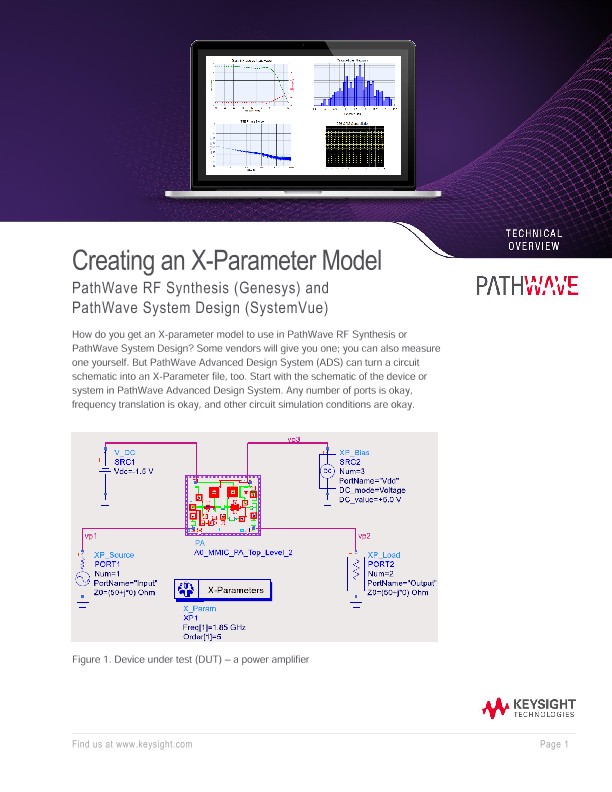
Figure 1 shows the DUT— a power amplifier— surrounded by special parts from the SimulationX_Param palette. These parts correlate to similar parts for a Harmonic Balance simulation.
• The XP_Source acts like a P_nTone.
• The XP_Load acts like a Term.
• The X-Parameters controller is like an Harmonic Balance controller.
• And finally, the XP_Bias is simply a V_DC.
All these parts have one thing in common: they can be swept. So when we extract a model from this test bench we can do it over frequency, power, load impedance, bias voltage… and we can even apply multiple tones to the input for an n-tone model. In our example, the source is set (Figure 2) for a harmonic index of 1, which corresponds to: 1 * Freq[1] = 1.85 GHz. Additional tones can be added to this source, just like in a P_nTone. As seen in Figure 2, the power level is swept from -40 to +10 dBm.
The load in this example is set to a constant 50 ohms, but you can specify 1) a swept impedance, for a load-pull measurement; and/or 2) a different impedance at each harmonic of the input signal.
The XP_Bias is set to +5 V and is applied to a third pin on the DUT. Therefore, our X-parameter model will have three ports: the RF input, the RF output, and the Vdd pin. This will be important if we want to monitor supply current in a power-added efficiency (PAE) simulation later on. This voltage can also be swept to extract a model over bias.
Finally, the X-Parameters controller looks a lot like Harmonic Balance, with the added field Output GMDIF file at the top of its dialog box (see below). This is the X-parameter file that will be generated after we run the simulation.
It’s important to check this box and fill in this field with a file name. Other than this, the controller is set to Freq[1] = 1.85 GHz with MaxOrder = 5, so we’ll capture up to 5th order harmonics and intermods in our model.
After simulation, the X-parameter file is saved, and you can open it with a text editor.
The file header tells us the conditions under which the model was extracted. We see (Figure 3) the number and frequency of the tones, the bias voltages, the power sweep values, etc.