Guide
Understanding Mutual Inductance: Key Concepts Explained For Electrical Engineers


Introduction
Ever wondered how a changing current in one coil can cause a voltage to appear in another, even when they aren’t physically connected? That’s mutual inductance—the principle behind transformers, wireless charging systems, and many communication circuits.
In practice, applying mutual inductance is not as simple as the textbook diagrams suggest. Engineers often face challenges such as estimating coupling in irregular geometries, preventing unwanted interference, and making sense of measurements that don’t match theoretical models. Without a clear approach, these issues can lead to inefficiency, reliability problems, and compliance hurdles in electromagnetic compatibility testing.
A deeper understanding of mutual inductance gives you the ability to design transformers and coils with greater precision, control noise before it becomes a problem, and improve wireless power transfer efficiency. It also helps preserve signal integrity in high-speed and RF applications where even small coupling effects can have a big impact.
This guide covers the fundamentals of mutual inductance, provides practical calculation methods, and shows how to apply them in real-world circuit analysis. You’ll find troubleshooting techniques, advanced tips, and examples from power electronics, communications, and automotive systems.
With the right tools, from oscilloscopes for measurement to signal generators for testing, you can move from theory to accurate, repeatable results with confidence.
Background and Context
Mutual inductance is the phenomenon where a changing current in one conductor induces a voltage in another nearby conductor through a shared magnetic field. To understand it properly, it helps to define the related concepts first:
- Self-inductance: The property of a single coil or conductor to oppose changes in its own current by inducing a voltage within itself.
- Magnetic flux: The total magnetic field passing through a given surface area, acting as the bridge between electrical current and magnetic field strength.
- Faraday’s law of electromagnetic induction: States that a change in magnetic flux through a loop induces an electromotive force (EMF) in that loop.
- Mutual inductance: Extends Faraday’s law to two or more conductors, where the magnetic field generated by one induces a voltage in another.
Why It Matters in Electrical Engineering
Mutual inductance is central to the operation of:
- Transformers: Efficiently transferring energy from one coil (primary) to another (secondary).
- Wireless charging systems: Enabling contactless energy transfer.
- Inductive sensors: Detecting changes in position, proximity, or magnetic properties.
- Coupled circuits in communications: Allowing intentional signal transfer or coupling across circuits.
It’s also a factor in EMI (electromagnetic interference), where unwanted coupling between conductors can degrade system performance.
Common Misconceptions
Several myths can cause engineers to misapply mutual inductance principles:
- It only relates to transformers. In reality, mutual inductance occurs in any conductors with changing currents and overlapping magnetic fields.
- Perfect coupling (k = 1) is common. In practice, geometry, spacing, and materials almost always reduce the coupling coefficient.
- It’s always beneficial. While it can improve efficiency and signal transfer, it may also introduce unwanted noise or cross-talk.
What You Should Already Know
Before working through this guide, you should be familiar with:
- AC circuit theory fundamentals
- The concept of inductance and its role in circuit design
- Basic calculus for understanding rates of change in current and magnetic flux
If you need a quick refresher, review oscilloscope basics for circuit measurement techniques and our inductance overview for the foundational theory.
Step-by-Step Instructions
Calculating and applying mutual inductance in real-world circuits involves a sequence of measurable steps. The workflow begins with defining your coil geometry, then calculating self-inductances, determining the coupling coefficient, computing mutual inductance, and finally applying it in your circuit analysis. Following this method ensures your results are both theoretically correct and validated in practice.
Step 1: Define Coil Geometry and Setup
The accuracy of your calculations depends heavily on how well you define the physical setup. Identify:
- Coil shape. It may be circular, rectangular, or solenoidal.
- Orientation. Coils can be parallel, coaxial, or angled relative to each other.
- Number of turns. More turns generally increase inductance.
- Spacing. The distance between coils has a direct impact on coupling.
- Core material. Different materials affect magnetic permeability and how flux is distributed.
Tip: Use precise measuring tools (calipers, rulers, or 3D CAD data) to capture dimensions accurately before starting any calculations.
Outcome: A complete physical description of your coil system, ready for inductance calculation.
Step 2: Calculate Self-Inductances (L1 and L2)
Self-inductance depends on coil dimensions, turns, and the core material’s permeability. A basic solenoid formula is:
Where:
- μ0 = permeability of free space (4π × 10⁻⁷ H/m)
- μr = relative permeability of core material
- N = number of turns
- A = cross-sectional area of coil (m²)
- ℓ = length of the coil (m)
Tip: Always account for the core permeability (μr), as it can change inductance by orders of magnitude.
Outcome: Accurate L1 and L2 values in henries, which will be used in later steps.
For more detail, see our inductance formula guide.
Step 3: Determine Coupling Coefficient (k)
The coupling coefficient measures how effectively magnetic flux from one coil links to the other:
In practice, you determine k through measurement or simulation. It depends on:
- Distance. Greater spacing reduces coupling.
- Alignment. Coaxial alignment yields higher coupling than angled or offset placement.
- Core material and geometry. High-permeability cores improve coupling.
Warning: k ranges from 0 (no coupling) to 1 (ideal coupling). Perfect coupling is extremely rare outside theoretical models.
Outcome: Estimated or measured coupling coefficient for your specific coil arrangement.
Learn more in our coupling concepts overview.
Step 4: Calculate Mutual Inductance
Once you have L1, L2, and k, the mutual inductance is straightforward:
This gives the mutual inductance in henries.
Tip: Validate your results using finite element simulations or with measurement tools such as an LCR meter or dedicated mutual inductance test setup.
Outcome: A precise value for M that you can apply in your circuit models.
Step 5: Apply Mutual Inductance in Circuit Analysis
With M known, incorporate it into your circuit equations to predict induced voltages and currents. This is especially important in:
- Transformer equivalent circuits
- Coupled inductor filter designs
- Wireless power transfer models
Two important concepts to include:
- Dot convention: Indicates polarity of induced voltages; aligning dots means voltages aid each other, opposite dots mean they oppose.
- Lenz’s law: The induced EMF always opposes the change that created it.
Outcome: An accurate model predicting how mutual inductance will influence your system’s performance.
Troubleshooting
Even with careful calculations, mutual inductance setups can produce results that don’t match expectations. Recognizing the most common issues and applying targeted fixes will save time and improve measurement accuracy.
| Issue | Likely Cause | Suggested Fix |
|---|---|---|
| Unexpected polarity flips | Incorrect coil wiring or dot convention mismatch | Reverse coil leads or adjust connections to match intended polarity |
| Weak or no induced voltage | Excessive spacing, poor alignment, or low coupling coefficient | Reduce coil separation, improve alignment, or use higher-permeability core |
| Measurement inconsistencies | Unstable test setup or inconsistent probe placement | Secure coils and probes, maintain consistent measurement procedure |
| Noise and interference problems | EMI from nearby devices or lack of shielding | Add magnetic/conductive shielding, increase distance from noise sources |
For consistent and accurate testing, follow best practices such as using stable setups, referencing guides like how to measure current with a multimeter, with a multimeter, and evaluating signal integrity to identify potential noise sources.
If repeated adjustments don’t solve the problem, deeper issues such as material inconsistencies, parasitic effects, or faulty equipment may be to blame. In those cases, consulting an experienced engineer or using precision lab-grade tools can help identify and resolve the root cause.
Advanced Tips and Variations
Once you’ve mastered the fundamentals, you can refine your approach to mutual inductance with advanced techniques that improve accuracy, efficiency, and performance in demanding applications.
Using Finite-Element Analysis (FEA) for Detailed Modeling
Finite-element analysis provides a powerful way to visualize magnetic field interactions and predict mutual inductance in complex geometries.
It accounts for 3D coil arrangements, non-uniform materials, and real-world boundary conditions that basic formulas cannot capture. For an in-depth look at this method, explore advanced mutual inductance simulation tutorials.
Reducing Parasitic Mutual Inductance on Dense PCBs
On compact PCB layouts, unintentional coupling between traces can cause signal integrity and EMI issues. Strategies to reduce this include:
- Increasing physical separation between sensitive traces
- Routing perpendicular signal paths across layers
- Adding ground planes or guard traces for shielding
For deeper insight into EMI challenges, see our EMI testing guide.
Leveraging Mutual Inductance in Wireless Charging
In wireless charging systems, coil geometry and alignment are optimized to achieve high coupling efficiency while maintaining safe operating conditions. Simulation and real-world measurement help fine-tune alignment tolerances and operating frequencies for maximum transfer efficiency.
Air-Core vs. Ferrite-Core Coil Designs
- Air-core coils avoid core losses and saturations, making them suitable for high-frequency applications like RF coupling.
- Ferrite-core coils increase permeability and boost coupling but can introduce losses at higher frequencies. The choice depends on your operating frequency and loss tolerance.
Customizations for RF and High-Power Applications
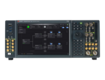
RF systems often require precision impedance matching, which can be evaluated using a network analyzer or network impedance analyzer to ensure optimal coupling. High-power designs may need larger core cross-sections, improved cooling, or reinforced insulation to handle increased thermal and electrical stresses.
Real-World Applications
Mutual inductance plays a pivotal role across multiple industries, shaping the performance, efficiency, and reliability of electrical systems.
In power transformers and inductors, precise control of mutual inductance ensures efficient energy transfer and minimal losses. Automotive systems, for example, rely on optimized transformer designs for onboard charging and DC-DC conversion, an area where tools like an automotive oscilloscope are invaluable for performance validation.
Wireless charging systems use tightly coupled coils to transfer power without direct electrical contact. Whether charging consumer electronics or electric vehicles, engineers fine-tune coil alignment, geometry, and operating frequency to maximize efficiency while meeting safety standards.
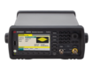
In communication circuits, mutual inductance enables intentional signal coupling between components, such as in RF filters or directional couplers. Testing these designs often involves high-frequency equipment like the E8257D PSG analog signal generator to generate stable, accurate test signals.
For EMI mitigation in PCB layouts, controlling unwanted mutual coupling between traces helps maintain signal integrity and regulatory compliance. Techniques such as careful routing, shielding, and impedance control are essential, supported by measurement tools that verify design performance.
Challenges in these applications include managing trade-offs between coupling efficiency and physical constraints, ensuring consistent results under varying environmental conditions, and balancing cost with performance.
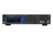
In power electronics, for example, engineers may use a DC power supply to replicate real-world load conditions during testing, ensuring designs perform reliably in the field.
These examples highlight that while mutual inductance offers powerful capabilities, it also demands careful measurement, simulation, and verification to achieve the desired outcome in practical systems.
Additional Resources
Expanding your understanding of mutual inductance is easier when you have the right tools and reliable sources of information.
Recommended tools include:
- Mutual inductance and impedance calculators for quick and accurate parameter estimates.
- LCR meters for precise inductance and coupling measurements.
- Oscilloscopes for waveform analysis and validation.
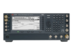
- Spectrum analyzers for evaluating frequency-domain effects of coupling, such as noise and harmonics—explore our spectrum analyzer buying guide.
- Simulation software like SPICE or finite-element tools for virtual prototyping.
Further reading might include textbooks on electromagnetics, advanced courses on transformer design, and peer-reviewed papers on high-frequency coupling effects. IEEE publications are a solid starting point for technical depth.
For community knowledge and practical troubleshooting, join active forums such as the Electronics Stack Exchange, where engineers share real-world insights, or IEEE communities focused on power electronics and RF design.
By combining these resources, you can bridge the gap between theory and hands-on application, improving both your understanding and your design outcomes.
Conclusion
Mutual inductance is a core principle that drives the performance of transformers, wireless charging systems, communication circuits, and EMI control. By defining coil geometry accurately, calculating self-inductances, and determining the coupling coefficient, you can apply these values in circuit analysis. This approach allows you to design systems that are efficient, reliable, and optimized for their intended application.
The best way to master it is through hands-on application. Use mutual inductance calculators to verify your calculations, test different coil configurations, and integrate advanced measurement tools into your workflow. Combining precise theory with real-world testing is what turns a good design into a great one.
Equip your lab with Keysight Premium Used Equipment to get like-new accuracy, extended warranties, and expert technical support—without the long lead times or high costs of new gear. Start building with confidence today.
Whenever You’re Ready, Here Are
5 Ways We Can Help You
Call tech support US: +1 800 829-4444
Press #, then 2. Hours: 7am – 5pm MT, Mon– Fri
Contact our sales support team
Create an account to get price alerts and access to exclusive waitlists
Talk to your account manager about your specific needs.
Frequently Asked Questions
How does the choice of core material impact mutual inductance in real applications?
Core material affects permeability and the magnetizing force needed to achieve a given flux. For example, a high-permeability magnetic core will increase the mutual inductance value between a primary coil and a secondary coil, especially in transformer designs.
What are the most common mistakes engineers make when measuring mutual inductance?
Misaligned coils, ignoring the influence of inductive reactance at higher frequencies, and not considering coaxial solenoids versus non-coaxial arrangements often cause inaccurate results.
Can mutual inductance be negative, and what are the practical consequences if it is?
Mutual inductance M is defined as a positive quantity, but the induced EMF can be positive or negative depending on the dot convention and current direction. This can reduce transfer efficiency or cancel intended coupling effects.
How do you effectively minimize unwanted mutual inductance in dense PCB layouts?
Increase separation between traces, use shielding, and route signals orthogonally. In some cases, isolating high-Alternating Current (AC) paths from Direct Current (DC) traces reduces interference from mutually induced EMF.
When is it necessary to use finite-element simulation rather than analytic formulas for mutual inductance?
When coil shapes are irregular, use multi-layer windings, or combine air gaps and magnetic cores, FEA models provide more accurate field mapping and mutual inductance values.
What is the practical range for the coupling coefficient (k) in typical transformer and inductor designs?
Well-coupled coils, such as closely spaced coaxial solenoids with a magnetic core, may reach k values above 0.95, while loosely coupled air-core systems might be below 0.5.
How does mutual inductance relate to electromagnetic interference (EMI) in high-speed circuits?
Unwanted coupling can introduce noise through mutually induced EMF, especially in systems with significant inductive reactance at high frequencies.
What diagnostic steps should be taken if circuit behavior suggests unexpected mutual coupling?
Check coil alignment, measure with calibrated tools, and confirm the mutual inductance value matches theoretical predictions. Using an oscilloscope to view induced waveforms in the secondary coil can help identify issues.
How does frequency affect mutual inductance, especially in RF and wireless charging applications?
As frequency increases, inductive reactance rises, and parasitic effects may reduce coupling. Both AC and DC bias conditions can alter performance, especially when the magnetic core is near saturation.
Which tools or instruments provide the most accurate mutual inductance measurements for engineers?
Precision LCR meters, oscilloscopes, and network analyzers are ideal for quantifying mutual inductance value, observing mutually induced EMF, and validating results under real AC and DC operating conditions.