
N1900 Series Physical Layer Test System (PLTS)
Flyers
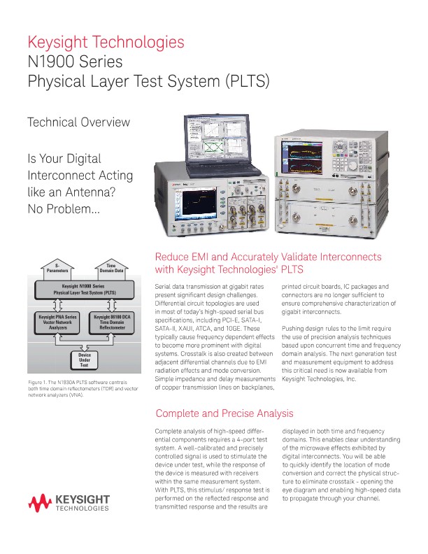
Reduce EMI and Accurately Validate Interconnects
with Keysight Technologies' PLTS
Serial data transmission at gigabit rates present significant design challenges. Differential circuit topologies are used in most of today’s high-speed serial bus specifications, including PCI-E, SATA-I, SATA-II, XAUI, ATCA, and 10GE. These typically cause frequency dependent effects to become more prominent with digital systems. Crosstalk is also created between adjacent differential channels due to EMI radiation effects and mode conversion. Simple impedance and delay measurements of copper transmission lines on backplanes, printed circuit boards, IC packages and connectors are no longer sufficient to ensure comprehensive characterization of gigabit interconnects. Pushing design rules to the limit require the use of precision analysis techniques based upon concurrent time and frequency domain analysis. The next generation test and measurement equipment to address this critical need is now available from Keysight Technologies, Inc.
Complete and Precise Analysis
Complete analysis of high-speed differential components requires a 4-port test system. A well-calibrated and precisely controlled signal is used to stimulate the device under test, while the response of the device is measured with receivers within the same measurement system. With PLTS, this stimulus/ response test is performed on the reflected response and transmitted response and the results are displayed in both time and frequency domains. This enables clear understanding of the microwave effects exhibited by digital interconnects. You will be able to quickly identify the location of mode conversion and correct the physical structure to eliminate crosstalk - opening the eye diagram and enabling high-speed data to propagate through your channel.
The Benchmark for All Physical Layer Measurements and Analysis
The N1930A PLTS software is used to control the test equipment by utilizing step-by-step calibration wizards for an intuitive user interface. This is helpful if you are not familiar with vector network analyzer measurement techniques. After the measurements are complete, the software is used to efficiently manage the large amount of data acquired during the 4-port measurement process. The software will do all the number crunching while you save your valuable time in the measurement laboratory for analysis. A large variety of export formats are supported to allow your favorite simulator to use the accurate 4-port data file to model the performance of your interconnect. This helps protect your investment in your existing modeling tools.
Critical Measurements in Your Signal Integrity Laboratory
Differential impedance and eye diagrams continue to be very important to characterize performance of high-speed digital components. However, the advent of microwave effects requires new figures-of-merit for the digital designer.
Discovering that your stripline and microstrip channels unexpectedly perform differently from one another at the last minute can be a disaster. Differential insertion loss (SDD21) is the frequency response seen by the differential signal as it propagates through the device. This microwave measurement is now deemed as mandatory data for characterizing channels in many digital standards committees. Another important measurement in the SI lab is mode conversion.
If your differential transmission line has any geometric asymmetries like vias, jags, bends or skew, then the differential signal will most likely generate a common mode signal and radiate crosstalk voltage to adjacent lines. This will undoubtedly lead to degraded eye diagrams and poor highspeed performance.