Confirm Your Country or Area
Please Confirm
Confirm your country to access relevant pricing, special offers, events, and contact information.
What are you looking for?
Making high speed measurements when downloading waveforms
Note: This applies to the 34980A
Waveforms are often used in test programs to simulate a sensor input to a device under test. Creating unique waveforms for an application can be done quickly through a number of sources including the 34980A’s DAC module. However throughput can be greatly affected by the number of times the program must download waveforms.
You can utilize the capabilities of the 34980A DAC card as an effective means of outputting waveforms. The 34951A is a four channel isolated Digital-to-Analog Converter (DAC). The independent channels output DC voltage up to ±16V or DC current up to ±20 mA. You can combine multiple DACs to get up to ±64 V on a module, as the modules are electrically isolated.
Each channel can be controlled manually or with the onboard memory to store multiple sequenced points. The internal point storage allows you to specify the provided sine, square, ramp, or triangle wave shapes with the TRACe[:DATA]:FUNCtion command. You can also create your own waveform with up to 512,000 points. The module can output points with a settling time of 40 µs and a 200 kHz point-to-point update rate.
You can create up to 32 voltage or current waveforms using the DAC module’s memory. Different waveforms can be output on each of the four channels, or the same waveform output on multiple channels. Additionally, a gain, offset, and frequency can be specified for each channel.
Whenever power is cycled or the *RST command is sent, the data stored for the waveforms will be cleared.
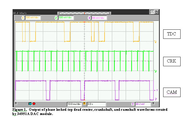
Suppose we want to create three phase-locked waveforms such as those used to simulate cam, crank, and top-dead-center sensor outputs in a car. The crankshaft (CRK) converts the up and down motion of the pistons into circular motion. The camshaft (CAM) opens and closes the intake and exhaust valves, moving them up and down. Top-dead-center (TDC) is the point where the piston starts descending and the intake valve opens. The crank makes two full rotations (720°) in the time it takes the cam and top-dead-center to each rotate once (360°). This corresponds to the camshaft opening and closing both the intake and exhaust valves. Sensors on the cam and crank generate pulse trains as shown in Figure 1. Note that this example simulates four cylinders. So for two rotations of the crank (entire crank waveform seen in Figure 1), each cylinder will display one pulse of the cam and top-dead-center.
The first segment of code displayed below initially defines the binary points of these waveforms through a series of if-else statements. A subroutine is then called, as shown in the second segment of code below, to set the parameters such as gain, offset, and frequency. The waveform data is first converted to a string and assigned a name and the DAC slot number. It is at this stage that multiple waveforms can be created and assigned to the DAC, unrelated to a specific channel. Next they are assigned to one of the four DAC channels. Last of all, the output and trace mode are enabled on the channels, and the DAC outputs the waveforms. Once you enable the output and trace mode on the channels, you can switch to other previously downloaded waveforms on the fly by assigning them to a channel. If a waveform is allocated to a channel, and then a different waveform is assigned to the same channel, the first waveform will be overwritten when the output is enabled. The waveforms in Figure 1 are phase locked, as they each have the same number of points and use the same internal clock.
 |
|
The following is Visual Basic code using T&M Toolkit for example test program. This segment creates the data points for the three waveforms.
Imports Keysight.TMFramework
Public Class Form1
    Inherits System.Windows.Forms.Form
    Dim instrument As Keysight.TMFramework.InstrumentIO.DirectIO
    Dim x(359), y(359), z(359) As Short
    Dim i, j, k As Integer
instrument = New Keysight.TMFramework.InstrumentIO.DirectIO("GPIB0::9::INSTR", False, 2000)
Sub Create_Waveforms()
        With instrument
            .WriteLine("*rst")

            'TDC data points
            For i = 0 To 359
                If ((i = 1 Or i = 0) Or (i <= 55 And i > 25) Or (i <= 235 And i > 205)) Then x(i) = "0"
                Else : x(i) = "32000"
                End If
            Next i
            'CRK data points
            For k = 0 To 359
                If (((k Mod 30) = 0) Or (((k + 1) Mod 30) = 0)) Then
                    z(k) = "0"
                Else : z(k) = "32000"
                End If
            Next k
            'CAM data points
            For j = 0 To 359
                If ((j <= 95 And j > 75) Or (j <= 275 And j > 255)) Then y(j) = "0"
                Else : y(j) = "32000"
                End If
            Next j

            Download_Waveforms()
        End With
    End Sub
This segment of code sets up the traces, defines the channels, and enables outputs:
Sub Download_Waveforms()
        With instrument
            .AutoFlush = False
            .Write("trac:dac 1, TDC, ")
            .AutoFlush = True
            .WriteIeeeBlock(x)
            .AutoFlush = False
            .Write("trac:dac 1, CRK, ")
            .AutoFlush = True
            .WriteIeeeBlock(z)
            .AutoFlush = False
            .Write("trac:dac 1, CAM, ")
            .AutoFlush = True
            .WriteIeeeBlock(y)
            .WriteLine("sour:func:trac TDC, (@1001)")
            .WriteLine("sour:func:trac CRK, (@1002)")
            .WriteLine("sour:func:trac CAM, (@1003)")
            .WriteLine("outp:stat on, (@1001, 1002, 1003)") 'enable outputs
            .WriteLine("sour:func:enab on, (@1001, 1002, 1003)") 'enable trace mode
            .WriteLine("Source:Mode Voltage ,(@1001, 1002, 1003)")
            .WriteLine("Source:Function:Volt:Gain 1,(@1001, 1002, 1003)")
            .WriteLine("Source:Function:Volt:Offset 0,(@1001, 1002, 1003)")
            .WriteLine("Source:func:Frequency 555.55,(@1001, 1002, 1003)")

        End With
    End Sub
End Class
When using many waveforms in a test program, it is important to download them all prior to execution time. This will improve throughput by saving execution time of the main test loop. Put up to 32 waveforms in the DAC’s memory, and select the desired waveform when needed on the fly. It is not necessary to create the waveform in the program at the moment it is needed. Simply assign the waveform to a channel when ready.
The SOURce:FUNCtion:FREQuency command sets the frequency of trace waveform outputs. The frequency in this example is used as a means to adjust the simulated speed/movement of the camshaft, crankshaft, and top dead center. One RPM equates to 12 pulses of the crank per minute. Therefore, one RPM corresponds to 1/5 Hz. The 34951A has a maximum point-to-point rate for trace waveforms of 200kHz. Thus, the maximum frequency = 200,000 / number of points. Since each waveform has 360 points, the maximum frequency allowed is 555.56 Hz, which simulates about 2800 RPM.
Since the download rate is approximately 10,000 points per second, traces containing a large number of points will take a considerable amount of time to download. When downloading large traces, increase the timeout value of your programming application and use the *OPC? command to verify the completion of the download. A total of 1,080 points were used in this example. Entering these points in the trace as a very long string took about 100 ms to run versus using a binary block of shorts (two bytes), which only took about 30ms. Consider these types of format options when creating your waveforms.