


- Overview
- All Models
- Support
Validate mmWave protocol conformance and MIMO performance
The Keysight multi-probe anechoic chamber (MPAC) family delivers a comprehensive solution for mmWave over-the-air (OTA) testing, enabling accurate validation of protocol conformance and MIMO performance. These systems support direct far-field measurements, multi-angle and multi-beam analysis, and full spherical coverage, ensuring realistic and repeatable test conditions. Optimized for 5G NR FR2, beamforming, and radio resource management (RRM) validation, MPAC systems also support sub-6 GHz signaling, providing flexibility across a wide range of test scenarios. The chambers feature advanced multi-probe configurations, integrated positioning and alignment tools, low path loss, and a modular architecture that enables easy setup, scalability, and future expansion. MPAC configurations can be tailored to your specific needs—from compact setups for protocol verification to fully equipped systems for comprehensive 3D MIMO performance evaluation of the device under test (DUT). Need help selecting? Check out the resources below.
Probe architecture
Achieve high measurement throughput with optimized multi-probe layouts designed for rapid beam acquisition and minimal test time.
Beam analysis
Evaluate complex beamforming behavior with support for multi-beam, multi-angle, and dynamic beam tracking in realistic OTA environments.
Measurement accuracy
Ensure repeatable results with low path loss design, stable chamber environments, and precise probe positioning.
Throughput optimization
Accelerate validation cycles with fast switching, parallel measurements, and automated test execution.
-
Maximum angles of arrival
3 to 8
-
Frequency range
600 MHz to 8,000 MHz, 22 GHz to 50 GHz, 24 GHz to 50 GHz
-
Measurement type
Direct far field (DFF)
-
Maximum DUT weight
5 kg to 12 kg
-
Range length
1 m to 1.06 m
-
Use cases
Protocol Verification, Protocol Acceptance, Functional, Performance, MIMO Performance, RRM 2AoA Verification, RRM 2AoA Acceptance
Available products
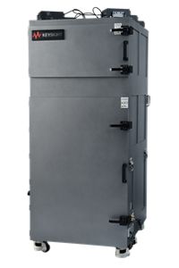

2D Multi-Probe Anechoic Chamber (MPAC) Pro
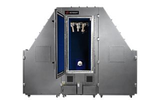

3D Multi-Probe Anechoic Chamber (3D MPAC)
Services and support
Innovate at speed with curated support plans and prioritized response and turn-around times.
Get predictable, lease-based subscriptions and full lifecycle management solutions—so you reach your business goals faster.
Experience elevated service as a KeysightCare subscriber to get committed technical response and more.
Ensure your test system performs to specification and meets local and global standards.
Make measurements quickly with in-house, instructor-led training, and eLearning.
Download Keysight software or update your software to the newest version.
Frequently asked questions
In over-the-air (OTA) testing, “multi-probe” refers to a chamber setup that uses an array of fixed probes, typically antennas, placed around the device under test. Instead of rotating the device or a single measurement antenna to capture performance in different directions, the probes can simultaneously or sequentially capture radiation patterns, throughput, or other metrics from multiple angles.
This approach significantly reduces measurement time compared to mechanical scanning systems, since a large portion of the spatial field is covered at once. Multi-probe setups are particularly useful for evaluating devices that rely on complex antenna arrays or beamforming, where rapid changes in direction and phase must be captured accurately.
A 2D MPAC system arranges probes in a single plane around the device under test. This configuration is effective for measuring performance metrics such as total radiated power, total isotropic sensitivity, and throughput under simplified spatial conditions. It provides a balance between speed and accuracy and is often used for conformance or pre-compliance testing.
A 3D MPAC system extends probe placement to cover a full sphere around the device, allowing characterization of antenna patterns in all directions. This is critical for modern devices that use sophisticated beamforming or adaptive antenna techniques, since their performance can vary significantly depending on orientation and angle of arrival. The 3D configuration provides more complete data for evaluating coverage, efficiency, and spatial diversity, but requires a larger number of probes and more complex calibration.
At millimeter-wave (mmWave) frequencies, wavelengths are very short, meaning antennas and beams are more narrowly focused. To capture these sharp variations in radiation patterns, probes in the chamber must be spaced closely enough to resolve the fine angular detail of the beams. If probe density is too low, narrow lobes or sidelobes may be missed, leading to incomplete or inaccurate characterization of antenna performance.
Higher probe density ensures the chamber can resolve the true behavior of phased arrays and beam-steering systems, which are central to 5G and 6G designs. However, increasing density comes with trade-offs in terms of cost, chamber complexity, and calibration effort. Engineers must balance these factors depending on whether the goal is high-resolution characterization or faster, lower-complexity functional testing.
Calibration is critical in any OTA chamber, as it ensures the measured results represent the true performance of the device under test rather than artifacts of the test setup. In multi-probe systems, calibration aligns the relative gain, phase, and position of each probe so that measurements across the array are consistent and comparable.
Calibration accounts for factors such as probe placement errors, cable delays, chamber reflections, and frequency-dependent characteristics of the antennas. Without proper calibration, small inaccuracies can accumulate, especially at higher frequencies where tolerances are tighter, leading to misleading results. Regular calibration allows engineers to trust that changes observed in device performance are due to the device itself and not the test environment.