How to Debug Inverter Anti-Islanding Detection Algorithms

Investigate Island Detection Behavior
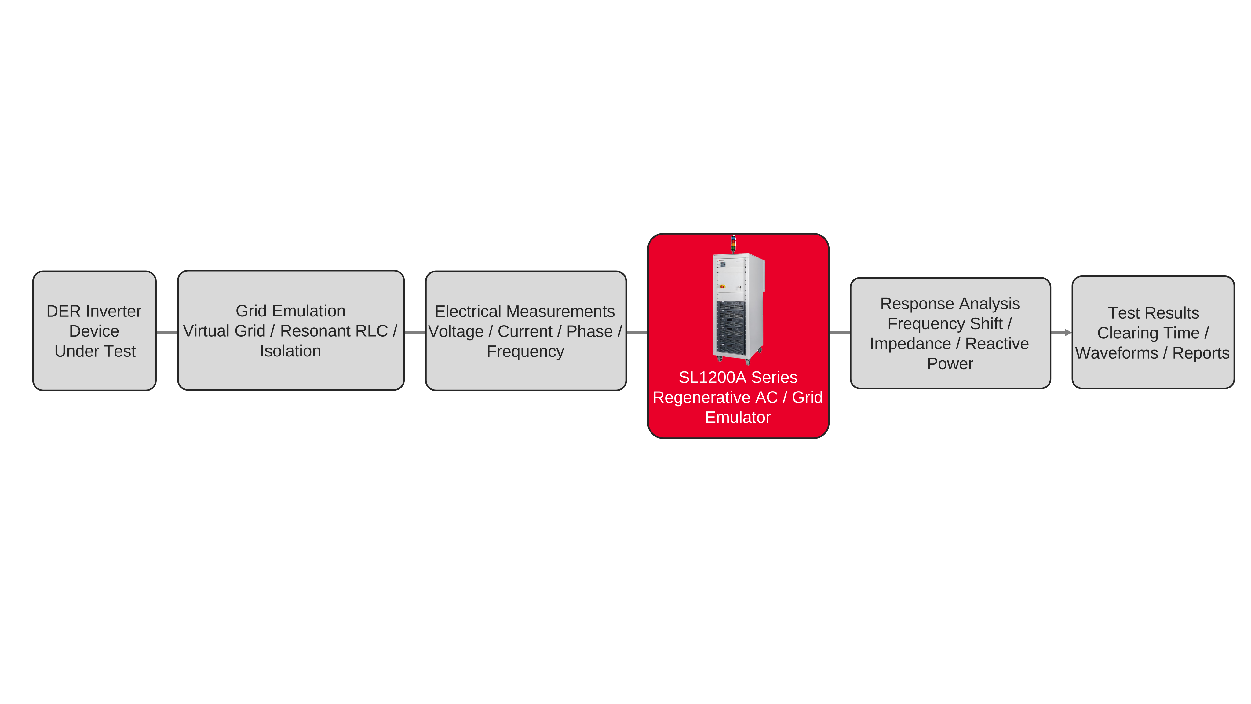
Anti-islanding algorithm debugging starts with a repeatable resonant island operating point and synchronized measurements of inverter voltage, current, phase, and frequency. During inverter protection testing, engineers first balance active and reactive power across the emulated island load and confirm low residual current through the simulated utility connection. After grid isolation, the island voltage is governed by the interaction of the inverter output and resonant impedance. This allows engineers to observe whether the inverter's control system causes a frequency excursion, a reactive-power perturbation, or another measurable response before protection operates. Frequency shift detection methods can be examined by capturing frequency trajectories and the elapsed time between isolation and shutdown under controlled test conditions.
Other detection approaches require different interpretations of the same electrical response. Grid impedance detection relies on observing the voltage response to an injected test-current stimulus, while reactive power modulation changes the island's apparent resonant condition and can produce frequency ripple. Engineers can compare measured trends across carefully selected island tunings, fundamental-frequency current balances, and programmed inverter operating points. The test system records voltage, current, phase, frequency, and shutdown timing, while proprietary internal controller quantities remain accessible only if the inverter exposes them separately. Automated Power Hardware-in-the-Loop conditions support anti-islanding algorithm debugging by keeping the external electrical environment repeatable as firmware settings or protection logic change.

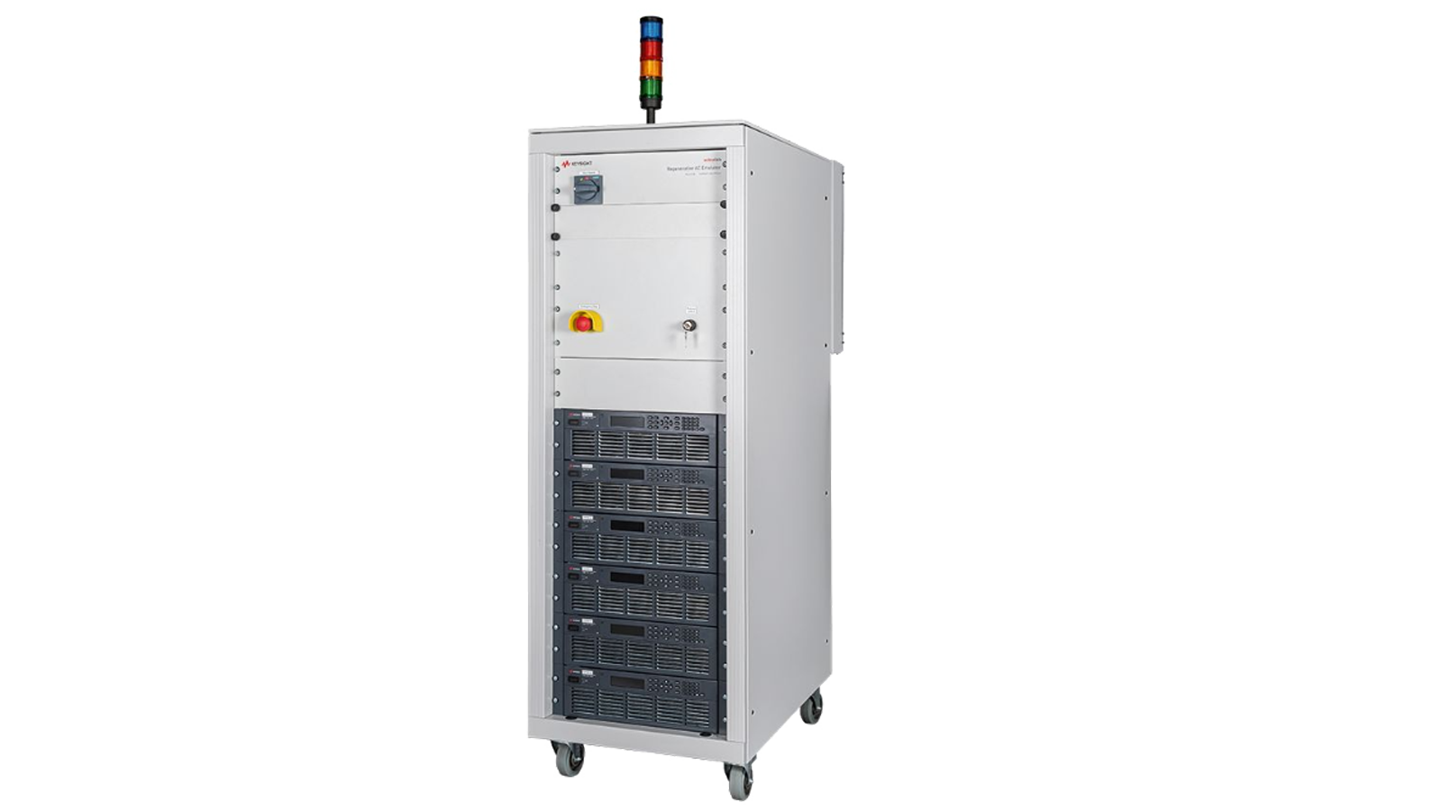
Anti-Islanding Algorithm Debugging Solution
See Block Diagram of Anti-Islanding Algorithm Debugging Solution

Explore Products in Our Anti-Islanding Algorithm Debugging Solution
-

![]()
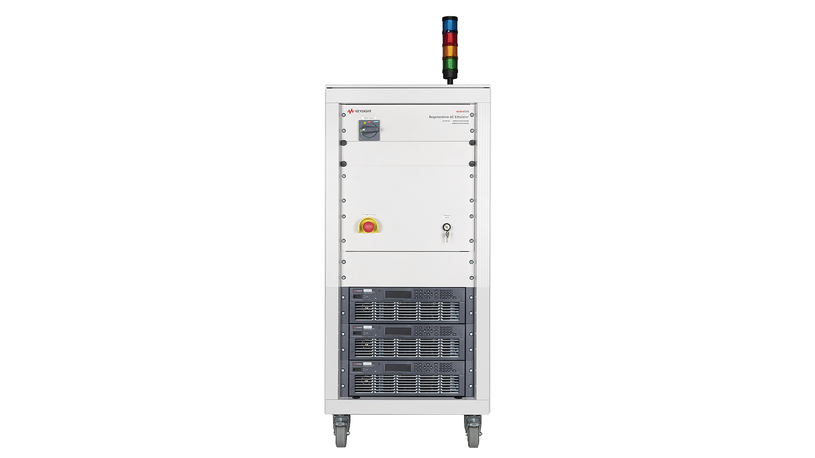
SL1201A Scienlab Regenerative AC Emulator, 600 VAC, 63 A, 30 kVA, 3‑Phase

Discover Resources and Insights
Additional Resources for Anti-Islanding Algorithm Debugging
Related Use Cases


-
![]()
Learn More
How to Emulate Partial Shading Conditions
Simulate partial shading in PV systems to validate inverter performance, MPPT behavior, and solar array efficiency under real-world conditions.
Learn More

-
![]()
Learn More
How to Simulate Battery Power Accurately
Simulate battery power behavior using DC supplies to validate IoT device performance under real-world conditions.
Learn More
-
![]()
Learn More
How to Simulate Degraded Photovoltaic Module Performance
Simulate degraded PV modules and mismatch conditions to evaluate inverter performance, MPPT accuracy, and solar system reliability.
Learn More

Get in Touch with One of Our Experts
Need help finding the right solution for you?