
N432A Thermistor Power Meter
기술 개요
Technical Overview
Introduction
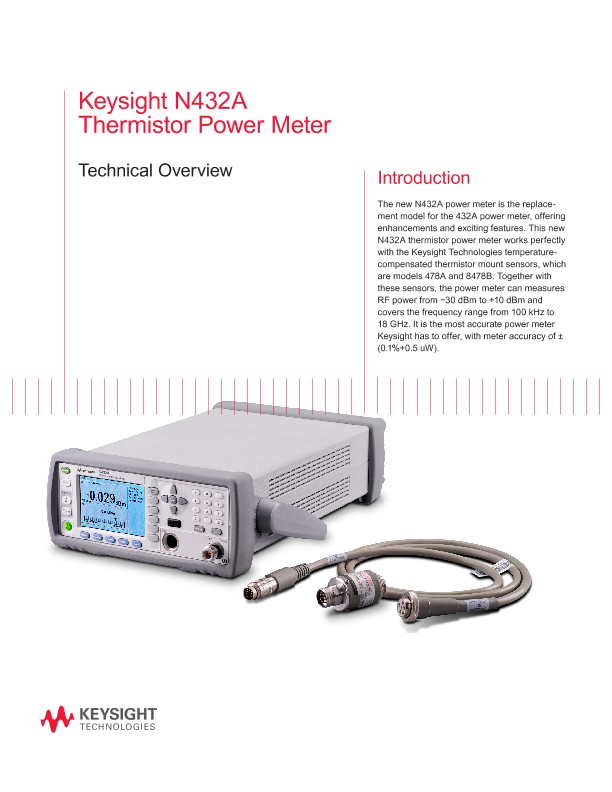
The new N432A power meter is the replacement model for the 432A power meter, offering enhancements and exciting features.
This new N432A thermistor power meter works perfectly with the Keysight Technologies temperature-compensated thermistor mount sensors, which are models 478A and 8478B.
Together with these sensors, the power meter can measures RF power from −30 dBm to +10 dBm and covers the frequency range from 100 kHz to 18 GHz. It is the most accurate power meter Keysight has to offer, with meter accuracy of ± (0.1%+0.5 uW).
Thermistor Mount
A thermistor is a resistor whose electrical resistance changes substantially with changes in temperature. Most thermistors are negative temperature coefficient (NTC) devices and are usually made of a metallic oxide compound.
This means the resistance of the thermistor decreases as temperature rises, as shown in the resistance-vs-temperature curve.
However, there are also thermistors which have positive temperature coefficient (PTC). In this case, the resistance increases when temperature rises. Currently, Keysight offers two RF power sensors based on the thermistor mount concept with NTC characteristics; they are 478A and the 8478B.
DC Self-Balancing Bridge
As mentioned earlier, the N432A operates on the basis of the Wheatstone self-balancing bridge shown in Figure 3. Starting from the thermistor mount, when RF power is applied to it, radiating heat will cause the thermistor resistance (RT) to decrease.
The bolometer current source (controlled by the differential amplifier) is then adjusted to decrease the bias until the resistance rises back to the value it had before power was applied. At this stage, the differential input of the amplifier are equal to zero.
The whole process creates a self-balancing bridge or auto null condition. The null condition is created when R1/RT = R2/R3. In the N432A power meter, R1 is the resistor value set by the user on the front panel to match the resistor of the thermistor mount sensor used.
Also, R2/R3 is equal to one as both resistors are 1 kΩ. The change of bias power required to restore the thermistor to the same resistance is therefore equal to the power dissipated in the thermistor mount.
Theory of Operation
Bridge circuits consist of two separate DC self-balancing bridges. The first bridge is called the RF bridge, detecting the RF power, and the second is called the compensated bridge, to compensate for environment temperature drift.
This is because the thermistor will have different characteristic curves at different ambient temperatures. The readings of the ambient thermistor are used to correct the readings of the sensor thermistor. This dual bridge operation is called compensated mode.
During operation, both bridges will be balanced as explained previously. Both voltages at the top of bridges, VRF and VCOMPENSATED will be fed to the signal conditioning block for buffering and gain adjustment, gain adjustment and then will be fed to the meter ADC. At the signal conditioning bock, V0 and V1 will be measured as well. The V0 and V1 are the voltages needed to compute the power measurement.
From Equation 1, V0 is the bridge voltage difference (VCOMPENSATED − VRF) when there is no RF power applied to the thermistor mount sensor. Conversely, V1 is the bridge voltage difference (VCOMPENSATED − VRF ) when RF power is applied. R is the thermistor resistance value. VCOMP0 is the VCOMPENSATED value when no RD power is applied to the thermistor mount sensor. Lastly, VCOMP1 is the VCOMPENSATED value when RF power is applied to the thermistor mount sensor.
The ADC digitizes all the voltage measurements from the DC bridges; the internal microprocessor will compute the power measurement and then display the results on the front LCD.
The users can select which measurement results to be displayed, from power measurement (dBm, Watts) to the voltage measurements (VRF , VCOMPENSATED , V0, and V1). This whole digitization works much like a built-in digital voltmeter (DVM) inside the N432A, and therefore it gives an equivalent 6.5 digit DVM voltage measurement.
However, there are some applications where more accurate measurement is needed. This is why the N432A still provides the voltages to be measured using external DVM at the BNC connector (rear panel of the meter).
The N432A also has a built-in range calibrator circuit to supply a DC source to the DC bridge during calibration. Calibration can be done periodically depending on the users requirements.
The calibration process refers to external DVM through (the rear panel of the meter VRF and VCOMPENSATED) BNC connections. The process calibrates the DC bridge circuit to the ADC block.
With this feature, users can calibrate the N432A on their site without sending it to the factory or service center. In most cases, the calibration process will be traceable via the DVM, using the Keysight 3458A Digital Multimeter, 8.5 digit.
N432A Application Example
One of the main applications of N432A is the calibration of the power meter reference calibrator, the 50 MHz, 0 dBm source. The measurement setup is shown in Figure 5 below. The external 3458A standard DMM is optional, and will depend on the test or the calibration requirement of the user.
The purpose of the test is to check whether the 50 MHz, 0 dBm reference calibrator is within the manufacturer specification. This is done because the N432A system (plus the 478A option H75 or H76) has a very low measurement uncertainty of less than 1%.
Hence the N432A system is suitable for testing and checking whether the power meter reference calibrator is within or beyond the specification. Normally, the lab operator will define statistically a detail measurement uncertainty calculation table to obtain the total uncertainty or error.