Choose a country or area to see content specific to your location
What are you looking for?
-
-
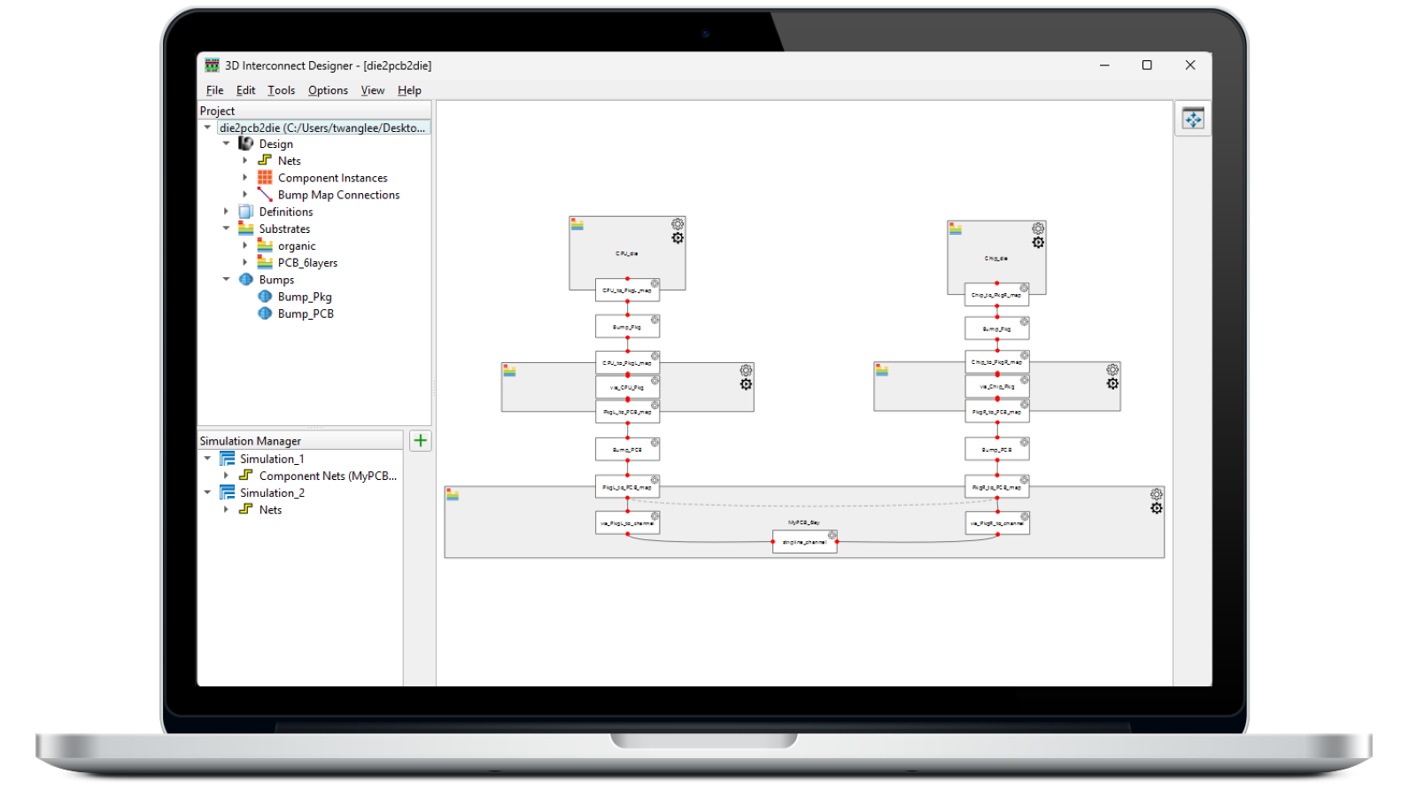
Accelerate Advanced Package & 3DIC Designs
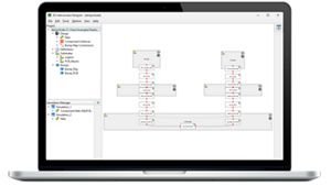
Design, model, and validate complex 3D interconnect architectures with a powerful standalone design environment.

-
Scale AI Compute. Simplify Validation.
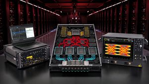
Automate transmitter and receiver validation across next-generation I/O, memory, and fabric interfaces.
-
End-to-End Validation for AI Data Center
Strengthen 1.6T network reliability for AI-scale workloads from transceivers to interconnects.

-
Take On Complex MIMO Signals
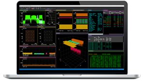
Pair Keysight VSA software with the new XA5 signal analyzer for advanced visualization, demodulation, and analysis — start your 30-day trial today.
-
Introducing AI-Enhanced Packet Brokers
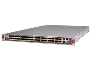
With extra memory and storage, these enhanced NPBs run Keysight's AI security and performance monitoring software and AI stack.
-
Accelerate Semiconductor Innovation
Explore end-to-end workflows spanning IC design, validation, wafer test, and photonics.

-
Trade In Before You Buy New
Save up to 50% on our latest instruments with eligible Keysight or competitor trade-ins.
-
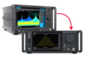
448 Gb/s Waveform Generation
Achieve 200+ Gbaud multi-level modulated signals with high-speed AWGs for digital and optical standards.
-
The Right Connection Makes the Measurement
Maximize accuracy and performance with precision accessories engineered for Keysight instruments.

Trade In Before You Buy NewSave up to 50% on our latest instruments with eligible Keysight or competitor trade-ins.
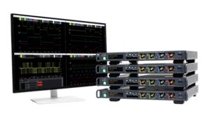
Scale to Hundreds of Channels. Keep Measurements in Sync.Four channels per 1U of rack space, up to 1 GHz bandwidth, and multi-oscilloscope synchronization.
-
-
Purpose-built solutions engineered for the design and test challenges unique to your industry.
Use Cases mapped to every stage of your product lifecycle, from design through operations.
Success Stories
Nokia + Keysight: AI Network Designs at Scale -
Authoritative application notes, data sheets, reference designs, and test procedures to accelerate design and validation decisions.
FeaturedHands‑on bootcamps that teach system design, test methods, and production workflows engineers can apply immediately.
Learning Hub
AI TechnologyExplore methodologies, test strategies, and technical resources for designing, validating, and scaling AI systems and networks.
-
Quick access to support related self-help tasks.
Additional content to support your product needs.
Do more with Keysight ServicesExplore services to accelerate every step of your innovation journey.






Accessories
Explore the complete portfolio of Keysight accessories designed to complement and extend your instruments. Use the filters below to quickly find compatible accessories such as modules, cables, adapters, and other system components to configure, expand, and optimize your test system for your specific measurement needs.


Showing 12 of 44
No Filter available
No Filter available
No Filter available


External DC Bias Adapter
16200B can operate with high frequency LCR meters and impedance analyzers that can supply a bias current across the device of up to 5 Adc with 7 mm port.
16200B can operate with high frequency LCR meters and impedance analyzers that can supply a bias current across the device of up to 5 Adc with 7 mm port.
External DC Bias Adapter
16200B
16200B can operate with high frequency LCR meters and impedance analyzers that can supply a bias current across the device of up to 5 Adc with 7 mm port.
The 16200B test fixture is designed to operate with high frequency LCR meters and impedance analyzers. It allows you to supply a bias current across the device of up to 5 Adc through a 7 mm port by using an external DC current source.


Magnetic Material Test Fixture
Measure the accurate permeability of toroidal-shaped materials in a wide range of sizes.
Measure the accurate permeability of toroidal-shaped materials in a wide range of sizes.
Magnetic Material Test Fixture
16454A
Measure the accurate permeability of toroidal-shaped materials in a wide range of sizes.
Frequency:
1 kHz to 1 GHz
Sample Size (Toroids Only):
height: ≤ 8.5 mm
inner diameter: ≥ 3.1 mm
outer diameter: ≤ 20 mm
The 16454A is designed for accurate permeability measurements of toroidal-shaped magnetic materials. Since the construction of this fixture creates one turn around the toroid (with no magnetic flux leakage), the need of winding a wire around the toroid is unnecessary. Complex permeability is calculated from the inductance with and without the toroid. When the E4991A/4291B with option 002 is used as the measurement instrument, direct readouts of complex permeability are possible. In addition, it is furnished with a small and a large fixture to adapt to a wide range of sizes.
For more information about Material Testing Equipment, please visit Materials Test Equipment and LCR Meter & Impedance Measurement Product Accessories


Dielectric Test Fixture
Evaluate the dielectric constant of solid dielectric materials; complies with ASTM D150
Evaluate the dielectric constant of solid dielectric materials; complies with ASTM D150
Dielectric Test Fixture
16451B
Evaluate the dielectric constant of solid dielectric materials; complies with ASTM D150
Frequency:
≤ 30 MHz
Measurement parameters:
capacitance (C), dissipation factor (D), and dielectric constant (εr', εr'')
Material-under-test size:
thickness: ≤ 10 mm
diameter: 10 to 56 mm
The 16451B is used to evaluate the dielectric constant of solid dielectric materials accurately, and complies with ASTM D150. The 16451B employs the parallel plate method, which sandwiches the material between two electrodes to form a capacitor. An LCR meter or an impedance analyzer is then used to measure the capacitance created from the fixture.
For more information about Material Testing Equipment, please visit Materials Test Equipment.
Learn more about LCR Meter & Impedance Measurement Product Accessories


Dielectric Material Test Fixture
Eliminate stray capacitance by measuring the dielectric constant of solid materials using the parallel plate method.
Eliminate stray capacitance by measuring the dielectric constant of solid materials using the parallel plate method.
Dielectric Material Test Fixture
16453A
Eliminate stray capacitance by measuring the dielectric constant of solid materials using the parallel plate method.
Frequency:
1 MHz to 1 GHz
Sample size (smooth sheets only):
thickness: 0.3 mm to 3 mm
diameter: ≥ 15 mm
The 16453A is designed for accurate dielectric constant and loss tangent measurements on the E4991A/4291A/B. It employs the parallel plate method, which sandwiches the material between two electrodes to form a capacitor. The E4991A/4291A/B measures the capacitance created from the fixture, and option 002 firmware calculates the relative complex permittivity as described in the 16451B. Adjustment to insure parallel electrodes is required when using the 16451B. This adjustment is not required with the 16453A because the fixture has a flexible electrode that adjusts automatically to the material surface.
For more information about Material Testing Equipment, please visit Materials Test Equipment.
Learn more about LCR Meter & Impedance Measurement Product Accessories


Test Fixture (SMD Components)
Perform impedance evaluation on a minimum SMD size of 1.6(L) x 0.8(W) [mm]
Perform impedance evaluation on a minimum SMD size of 1.6(L) x 0.8(W) [mm]
Test Fixture (SMD Components)
16034E
Perform impedance evaluation on a minimum SMD size of 1.6(L) x 0.8(W) [mm]
- Measurement instruments: 4192A, 4194A (impedance mode), 4263B, 4278A, 4279A, 4284A, 4285A, 4294A, E4980A
- Frequency: DC to 40 MHz
- DC bias: +/- 40 V peak max (AC+DC)
- Operating temperature: 0 to 55 oC
- Terminal connection: BNC, 4 terminal-pair
- Dimensions (approx.): 128(W) x 60(H) x 71(D) mm
- SMD Test Fixture Selection Table
The 16034E test fixture is designed for impedance evaluations of SMD components. The minimum SMD size that this fixture is adapted to evaluate is 1.6(L) x 0.8(W) mm.
Learn more about Keysight LCR Meter & Impedance Measurement Product Accessories


Spring Clip Fixture
Use this test fixture with parallel electrodes for impedance evaluation of both lead and SMD components.
Use this test fixture with parallel electrodes for impedance evaluation of both lead and SMD components.
Spring Clip Fixture
16092A
Use this test fixture with parallel electrodes for impedance evaluation of both lead and SMD components.
- Frequency: DC to 500MHz
- DC Bias: -40V to +40V
- Operating Temperature: 0 to 55degC (Same as for Measurement Instrument)
- Contacts the SMD with the parallel electrodes.
- It is also provided with another pair of electrodes for holding the lead components.
- Terminal Connection: APC-7
The 16092A test fixure is designed for impedance evaluation of both lead and SMD components. It is furnished with two modules that can be readily screwed onto the plate to measure either lead or SMD components.


Tweezers Contacts Test Fixture
Perform impedance evaluation on a minimum SMD size of 1.6(L) x 0.8(W) [mm]
Perform impedance evaluation on a minimum SMD size of 1.6(L) x 0.8(W) [mm]
Tweezers Contacts Test Fixture
16334A
Perform impedance evaluation on a minimum SMD size of 1.6(L) x 0.8(W) [mm]
The 16334A is designed for impedance evaluations of SMD. The minimum SMD size that this fixture is adapted to evaluate is 1.6(L) x 0.8(W)[mm]. The tweezer's contacts on this fixture makes it easy to hold the DUT.
Learn more about Keysight LCR Meter & Impedance Measurement Product Accessories


Parallel Electrode SMD Test Fixture, DC to 3 GHz
Perform accurate and repeatable measurements on SMD size of (0.6L ± 0.03) x (0.3W ± 0.03) x (0.27H to 0.33)
Perform accurate and repeatable measurements on SMD size of (0.6L ± 0.03) x (0.3W ± 0.03) x (0.27H to 0.33)
Parallel Electrode SMD Test Fixture, DC to 3 GHz
16196C
Perform accurate and repeatable measurements on SMD size of (0.6L ± 0.03) x (0.3W ± 0.03) x (0.27H to 0.33)
The 16196C surface mount devices (SMD) test fixture offers excellent repeatability and usability, with accurate correlation up to 3 GHz. 16196 series fixtures are custom designed to fit specific SMD sizes (see table below), and provide repeatable DUT positioning with reliable contacts to enable stable measurement results - reducing the possibility of operator-induced error. Traditionally, SMD inductor evaluation up to 3 GHz has been difficult to implement - now with the 16196 series, it’s easy to perform accurate and repeatable measurements.
| Applicable device sizes of the 16196 series | ||
|---|---|---|
| Model | Size code | Specification of size L x W x H (mm) |
| 16196A | 0603 (inch) / 1608 (mm) | (1.6 ± 0.15) x (0.8 ± 0.15) x (0.4 to 0.95) |
| 16196B | 0402 (inch) / 1005 (mm) | (1.0 ± 0.1) x (0.5 ± 0.1) x (0.3 to 0.6) |
| 16196C | 0201 (inch) / 0603 (mm) | (0.6 ± 0.03) x (0.3 ± 0.03) x (0.27 to 0.33) |
| 16196D | 01005 (inch) / 0402 (mm) | (0.4 ± 0.02) x (0.2 ± 0.02) x (0.11 to 0.22) |
Learn more about Keysight LCR Meter & Impedance Measurement Product Accessories


High Temperature Component Test Fixture
Measure both axial/radial leaded devices and SMD within the temperature range from -55 to +200°C.
Measure both axial/radial leaded devices and SMD within the temperature range from -55 to +200°C.
High Temperature Component Test Fixture
16194A
Measure both axial/radial leaded devices and SMD within the temperature range from -55 to +200°C.
The 16194A is designed for measuring both axial/radial leaded devices and SMD within the temperature range from -55 to +200degC.


40Vdc External Voltage Bias Adapter
Supply a bias voltage of up to +/-40V to a DUT by connecting an external DC voltage source to this adapter
Supply a bias voltage of up to +/-40V to a DUT by connecting an external DC voltage source to this adapter
40Vdc External Voltage Bias Adapter
16065C
Supply a bias voltage of up to +/-40V to a DUT by connecting an external DC voltage source to this adapter
- Measurement Instrument: 4263B, 4268A, 4278A
- Applicable Test Fixture: 16034E/G/H, 16044A, 16047A/C/D/E, 16048A/B/D/E and 16089A/B/C/D/E
- Frequency: 50 Hz to 1 MHz
- DC Bias: -40V to +40V
- Operating Temperature: 0 to 55 degrees C (same as for measurement instrument)
- Terminal Connection: 4 terminal-pair
- Terminal Connection to Test Fixture: 4 terminal-pair
The 16065C adapter is designed to operate specifically with the 4263A/B, 4268A and 4278A. By connecting an external DC voltage source to this adapter, a bias voltage of up to +/-40V can be supplied to a DUT. The DUT can be inserted by connecting any direct attachment 4 terminal-pair test fixture to the adapter.


200 Vdc External Voltage Bias Fixture
Measure a DUT with up to +/-200 V DC bias and also measure axial/radial lead components
Measure a DUT with up to +/-200 V DC bias and also measure axial/radial lead components
200 Vdc External Voltage Bias Fixture
16065A
Measure a DUT with up to +/-200 V DC bias and also measure axial/radial lead components
The 16065A test fixture makes it possible to measure a DUT with up to +/-200V DC BIAS. The same modules of 16047A/D can be used to allow measurements of axial/radial lead components.
Learn more about Keysight LCR Meter & Impedance Measurement Product Accessories


2m Port Extension Cable for Impedance Analyzer
Extend the measurement port with a BNC male connector board that allows attachment of user-fabricated test fixtures
Extend the measurement port with a BNC male connector board that allows attachment of user-fabricated test fixtures
2m Port Extension Cable for Impedance Analyzer
16048H
Extend the measurement port with a BNC male connector board that allows attachment of user-fabricated test fixtures
The Keysight 16048H test leads extend the measurement port with a four-terminal pair configuration. It is provided with a BNC male connector board to allow the attachment of user-fabricated test fixtures.
