Toggle Menu

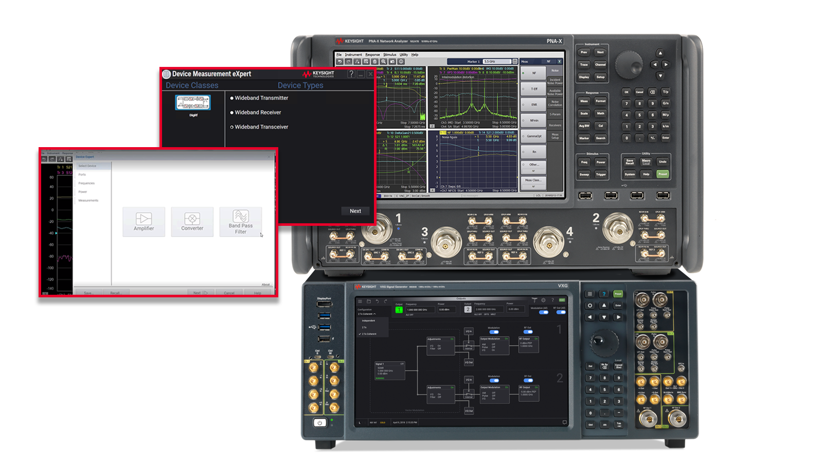
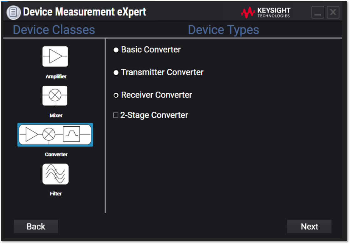
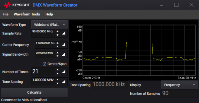
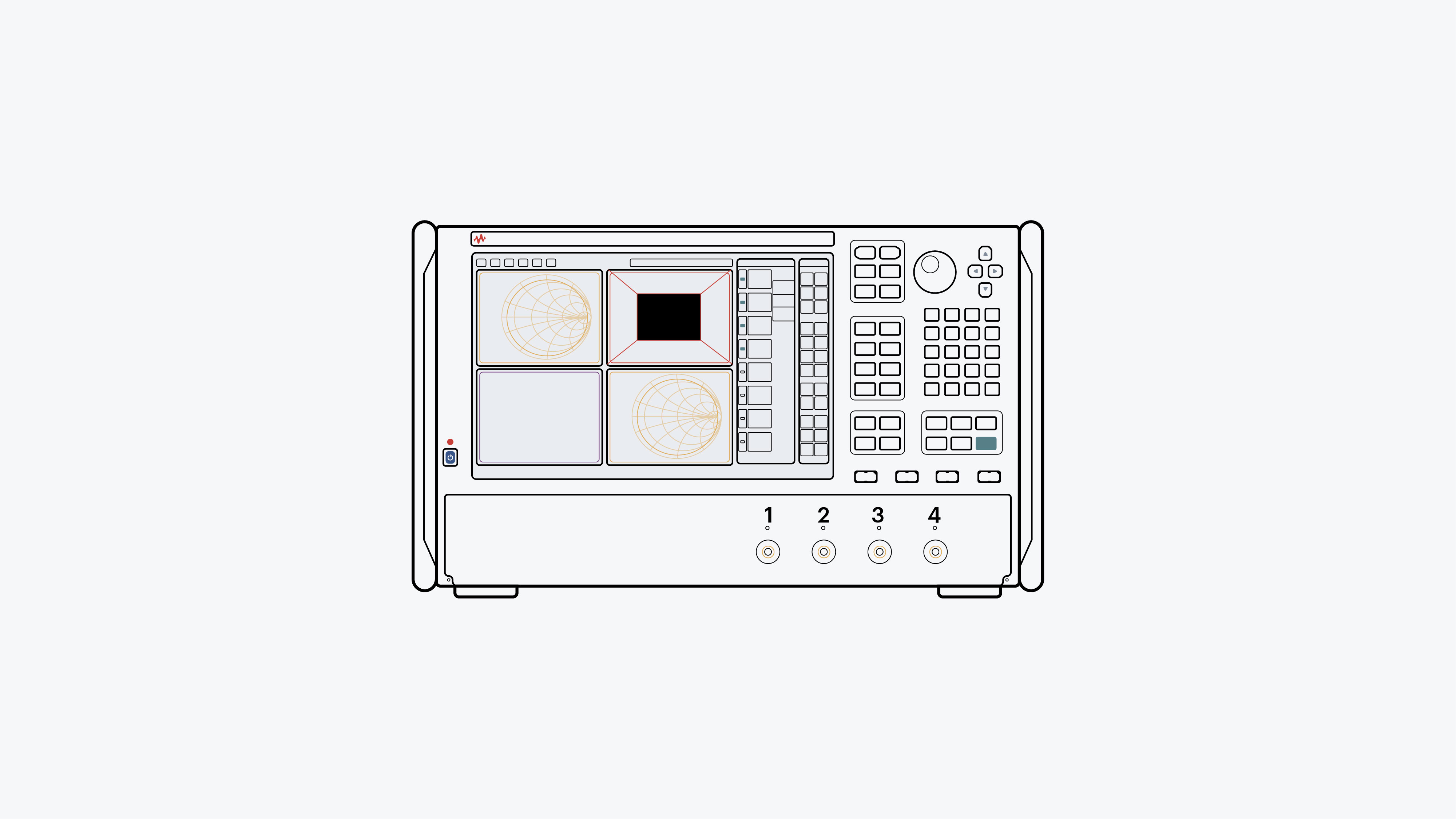
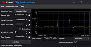
Digital-to-RF mixed devices require accurate characterization to reveal the true RF front-end performance of modern transmitters and receivers. You can achieve highly accurate frequency response measurements on digital-to-RF mixed devices using cross-domain stimulus response with a signal generator and network analyzer. In receiver measurements, the RF signal generator outputs the desired signal, and the receiver-under-test receives and digitizes the signal. Two independent systems handle these tasks. Test engineers must effectively integrate signal generation with RF instruments and signal reception with the receiver-under-test for spectral correlation. This cross-domain approach includes a wideband multi-tone stimulus capability with a wideband analysis technique to yield the device's frequency response.
To bridge the digital and RF domains, test engineers need RF signal analyzers and generators with digital data and control interfaces for the transmitters- and receivers-under-test. The test waveform (digital or RF) is precisely defined and repeatedly played for the response wave (digital or RF) and can be coherently correlated at each spectral component with the stimulus waveform. The result is vector response measurements between input and output signals within the stimulus waveform bandwidth. This cross-domain stimulus response methodology yields RF performance characteristics of digital and RF mixed devices over frequency or power ranges in one set of measurements.
Additional resources for digital wideband transceiver test
Analyzing the USB4 Type-C link requires oscilloscopes, a link fixture, and protocol triggering and decoding software to debug and optimize the connection. Learn how to establish a high-speed, crosstalk-limited, Type-C link quickly.
Learn more
![]()
Impedance mismatch characterization in high-speed digital application design and test requires understanding the reflection signals in both the time and frequency domain. Learn how to measure hot S-parameter and hot TDR measurement, including eye diagram, using a network analyzer.
Learn more
![]()
Characterizing the forward error correction (FEC) performance of hyperscale data centers requires visibility into all ethernet lanes to detect and correlate meaningful errors. Learn how to set up an FEC test to quantify the bit error rate (BER) and FEC performance of different devices in bursty Ethernet traffic.
Learn more
![]()

Need help finding the right solution for you?