How to Test a Digital Wideband Transceiver

Characterizing Digital Wideband Transceivers Using Digital / RF Cross-Domain Stimulus Response
Digital-to-RF mixed devices require accurate characterization to reveal the true RF front-end performance of modern transmitters and receivers. You can achieve highly accurate frequency response measurements on digital-to-RF mixed devices using cross-domain stimulus response with a signal generator and network analyzer. In receiver measurements, the RF signal generator outputs the desired signal, and the receiver-under-test receives and digitizes the signal. Two independent systems handle these tasks. Test engineers must effectively integrate signal generation with RF instruments and signal reception with the receiver-under-test for spectral correlation. This cross-domain approach includes a wideband multi-tone stimulus capability with a wideband analysis technique to yield the device's frequency response.
To bridge the digital and RF domains, test engineers need RF signal analyzers and generators with digital data and control interfaces for the transmitters- and receivers-under-test. The test waveform (digital or RF) is precisely defined and repeatedly played for the response wave (digital or RF) and can be coherently correlated at each spectral component with the stimulus waveform. The result is vector response measurements between input and output signals within the stimulus waveform bandwidth. This cross-domain stimulus response methodology yields RF performance characteristics of digital and RF mixed devices over frequency or power ranges in one set of measurements.
Digital Wideband Transceiver Test Solution
Characterize digital-to-RF mixed devices with Keysight’s digital wideband transceiver test solution.

Digital Wideband Transceiver Test Solution
Explore Products for Our Digital Wideband Transceiver Test Solution
-

![]()
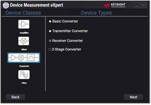
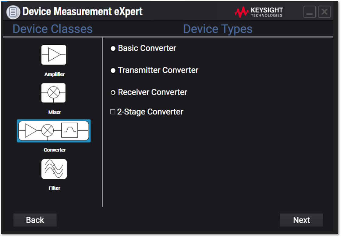
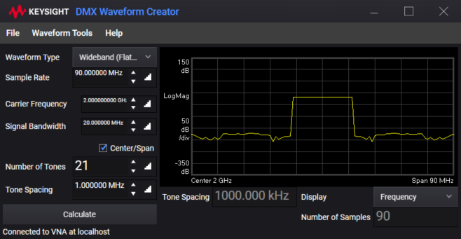
S94601B Device Measurement eXpert (DMX)
-

![]()
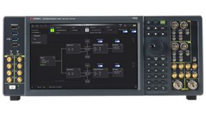
M9384B VXG Microwave Signal Generator
-
![]()
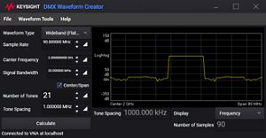
S94610B Digital Wideband Transceiver Analysis
-
![]()
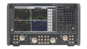
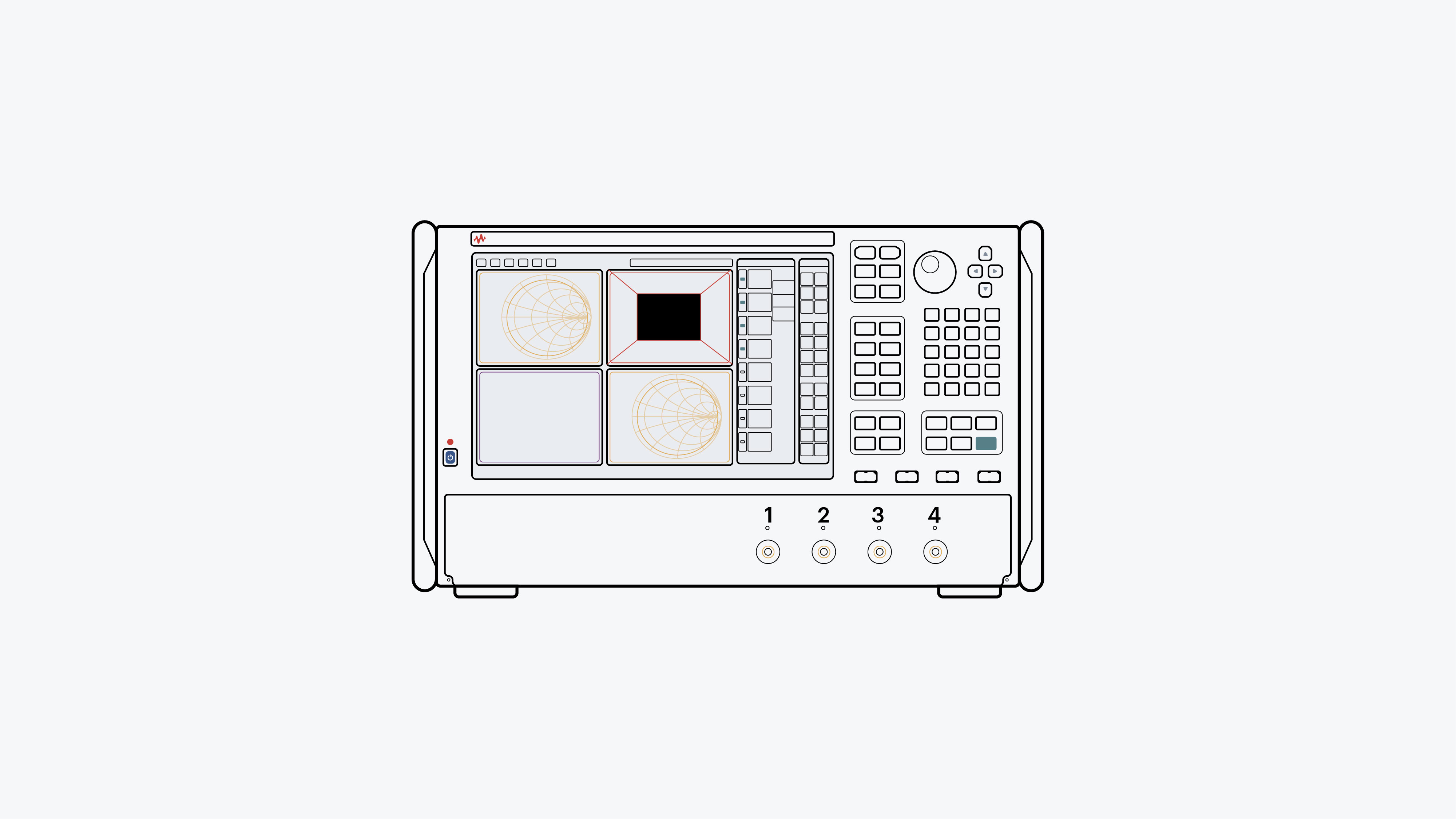
N5247B PNA-X Microwave Network Analyzer


Discover Resources and Insights
Additional Resources for Digital Wideband Transceiver Test
Related Use Cases
-
![]()
Learn More
How to Measure Frequency Converter Phase Noise
Measuring frequency converter phase noise requires the capture of many parameters, including gain, phase, delay, intermodulation distortion, and noise figure. Learn how to set up a test to characterize frequency converters using a combination of signal generation and analysis tools.
Learn More

-
![]()
Learn More
How to Characterize Low-Loss Materials for 5G
Characterizing low-loss materials for 5G requires understanding their electromagnetic properties. Learn how to determine permittivity, permeability, and other characteristics using a network analyzer and material measurement software.
Learn More
-
![]()
Learn More
How to Characterize 6G Components
Characterizing components at new sub-THz frequencies for 6G requires both S-parameter and wideband modulated measurements. Learn how to use a vector network analyzer and arbitrary waveform generator to make these measurements without introducing error.
Learn More

Get in Touch with One of Our Experts
Need help finding the right solution for you?