What are you looking for?
Introduction to Optical Design and Lens Design
Explaining What We Do: Gentle Introduction to Optical Design and Lens Design
What is optical design? How does it connect with other areas of optics, optical systems, and optical engineering? How do you do it?
These are the subjects of this “gentle introduction.” Our hope is to give you a flavor of what is involved, and to point you to other sources in case you want to learn more. Our business is based largely on what is commonly called lens design or (more correctly) optical design. This article is for the general reader who may be curious about this area of applied optics.
What Is Optics?
Optics is a branch of physics: the science of light. Optics is concerned with all aspects of the behavior of light and thus covers a lot of territory. Questions that range from “Why is the sky blue?” to “Why does a magnifying glass make things look bigger?” to “How does a laser work?" are all in the proper domain of the science of optics.
Although we usually think of visible light when we say “optics,” visible light is simply a narrow band of the electromagnetic spectrum, which ranges in wavelength from very short (such as X-rays) to medium (such as green light) to very long. Optics can help us with these other wavelength regions, but most of our discussion here will focus on the important and familiar visible spectrum. The visible spectrum includes the colors of the rainbow, from violet light with wavelengths near 400 nm (nanometer, or one-billionth of a meter) to red light near 700 nm. For comparison, X-ray wavelengths are in the nanometer range, while radio waves range from centimeters to meters in wavelength.


One interesting fact about light is that it acts sometimes like a wave, and other times more like a stream of very fast particles or quanta called photons. This wave/particle duality remains one of the mysteries of nature, but in practice we emphasize and use whichever aspect makes our calculations easier! In lasers and detectors, quantum effects are especially important, but in optical design, wave or "physical" optics tends to dominate.


Under the right circumstances, we can further simplify our calculations with the additional concept of light rays. Rather than thinking about waves propagating through space, we think about lines that are normal to the waves (i.e., traveling in the direction of the advancing wave front), and we call these lines light rays or simply rays. Some relatively simple equations can model the behavior of these rays (remember Snell's Law?), and much of optical design is therefore based on rays. This is called geometrical optics (don't worry, we still keep track of quantum and physical optics effects when needed to get the right answers!).
What Do Optical Engineers Do?
Optical engineers use optics to solve problems and to design and build devices that make light do something useful. This requires them to understand and apply the science of optics in substantial detail, in order to know what solutions are physically possible. They also must know what is practical in terms of available technology, materials, costs, design methods, and so on.
Optical engineers work in all areas of optics, using different techniques to design lasers, build telescopes, create fiber optics communication systems, and much more.
As with other fields of engineering, computers are important to most optical engineers. They use computers with instruments, for simulation, in design, and for many other applications. Engineers often use general computer tools such as spreadsheets and programming languages, and they also frequently use specialized software designed specifically for their field.
Need Help With Your Optical Engineering Challenges?
Explore Keysight's optical engineering services or contact an expert.
Lenses and Lens Designers
What is a lens? You might think this is a simple question — just a curved piece of clear glass or plastic, right?
Well, right — this is one type of lens, and the most common type at that (most eyeglass and contact lenses are this type).
To a lens designer, though, a lens is a more general device. It is any system that tries to collect and distribute light in a specifically desired way.
This is closer to what we think of when we discuss interchangeable “lenses” for a 35 mm SLR (single lens reflex) camera (e.g., normal, wide angle, telephoto, zoom). If you cut one open (don't try this at home, kids!), you'd find that such a camera lens contains multiple single “lenses” of different shapes and sizes. We refer to these as lens elements, and we call the complete lens an optical system.
Using this terminology, the lens designer today is more often called an optical designer, though the older term is still widely used, along with such whimsical, descriptive names as ray bender. It is increasingly common today for “lens designer” to be one of many titles worn by an optical engineering generalist. In addition, lens designers may or may not have a specific optics background — many people doing lens design today are physicists or other types of engineers by original training.
With this background, a lens (or optical system) can actually contain any number and combination of lens elements, mirrors, prisms, rotating polygon scanners, filters, diffraction gratings, holographic elements, and other sorts of optical components. The designer also has to think about what type of light source will flow through the lens (light bulbs, LEDs, lasers, stars, the sun, etc.). Also important is the type of detector, which is the device that reacts to light, such as film, photodetectors, CCD arrays, or the unsurpassed human eyeball.
Systems for infrared (IR) and ultraviolet (UV) light expand the number and types of sources and detectors we consider, but the principles are the same. Lens designers work frequently with IR and UV systems as well as with visible light. They often need to use special materials for IR/UV work because normal optical glass doesn't work well outside the visible spectrum.


The modern lens designer may work on "lenses" that are a long way from typical bifocals or pocket 35 mm camera (although the compact lens in a pocket camera can represent some clever design and cost-effective engineering). If a system uses light in some way (including any system that uses laser beams), lens design is almost certainly involved.


Figure 1. Image from the Hubble Space Telescope. Courtesy of NASA.
Some examples include:
- Microscopes, telescopes, and binoculars
- Camera lenses of all kinds (photo, video, zoom, etc.)
- Slide, movie, overhead, and video projectors
- Laser printers, office copiers, fax machines, and microfilm readers
- Endoscopes for minimally invasive surgery
- Laser-based optical readers for CD and CD-ROM
- Product code laser scanners in supermarkets
- Ultra-precise projector lenses used to make integrated circuits
- The Hubble Space Telescope (and its retrofitted repair optics)
- And many, many more...
The Hubble Space Telescope is perhaps the most famous space-based optical system, and several engineers at Optical Research Associates (ORA®, now known as Keysight Optical Design Engineering) actually worked on the design and other aspects of the repair optics. ORA even won a NASA award for this and other space-related work.
How to Design a Lens
Now that you know what a lens is, how do you design one? The full details are a bit beyond the scope of this "gentle introduction," but we can outline the typical steps.
- Problem definition: Other engineers or disciplines may define the requirements and boundaries of the design problem. Then, it is up to the lens designer to translate these into detailed optical specifications, such as field of view and focal length. You should also define the performance spec, which is a detailed description of how well an image the lens must form. There are various types of optical evaluation used for this purpose. You may have many requirements to meet, some of them contradictory in terms of how you approach the design (e.g., large aperture and light weight are usually opposing requirements that lead to tradeoffs and compromises).
- Pre-design: Once you set the basic factors, you have decisions to make, such as reflecting vs. refracting, number of elements, and overall size. Pre-design often involves paper and pencil sketching, including rough graphical ray tracing, with thin lenses standing in for real lenses. Graphical software tools can really help in this stage, especially when you need to make pre-design tradeoffs ("what-ifs"), as you often will.
- Starting point selection: Concept moves toward reality here, often with the help of an existing solution for a similar situation (books, patents, and your own company's previous work are rich sources). Software comes into play, since access to a database of existing designs can really speed up the selection process. You can also use graphical and approximate methods to create a starting point "from scratch," if necessary.
- Initial analysis: It helps to have a baseline analysis of the starting point so you can gauge improvement versus the spec. Aberration analysis may not be part of the spec, but it will probably be useful in the design process, especially in selecting variables for optimization.


- Optimization: Before you can optimize a lens, you’ll need to define a set of variables (parameters such as curvature, thickness, index of refraction, etc. that the program can change to try to improve performance), an error function (measure of optical quality, zero typically implying “perfection”), and constraints (boundary values that restrict possible configurations). You can then use numerical methods to alter the variables in systematic ways that attempt to minimize the error function while honoring all constraints. Sometimes it goes smoothly, more often it doesn't. Some software is pretty smart about many types of optimization problems, but no program is yet fully automatic, if only because some requirements and esthetic judgments may remain in the designer's head and not in the error function. This is when the lens designer’s guidance is important to resolve conflicts.
- Final analysis: After optimizing the lens, you need to see if it is actually doing what the original spec says it should do. Optimization error functions may not correlate perfectly with specifications such as Modulation Transfer Function (MTF) or encircled energy. If it's not quite there, you may have to go back and optimize more (perhaps adding variables or changing constraints). You may even have to find a different starting point in some cases.
- Prepare for fabrication: If the lens design meets its requirements, you will still have more work to do to prepare for fabrication. See "The Rest of the Story" (below) for a bit more on this subject.
What does this leave out? A lot of the “hard parts” of the design process, in fact. Incomplete or changing specifications. Conflicting requirements. Dead-end solution attempts. Unrealistic schedules. Computer crashes. Nobody said it was easy!
Explore Optical Design Software
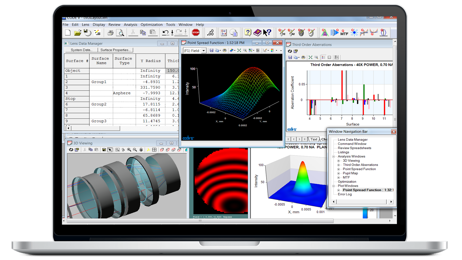
Model, analyze, optimize, and provide fabrication support for the development of optical systems with CODE V optical design software.
Overcoming Obstacles: Aberrations
Aberrations remained in comfortable obscurity up until the Hubble Space Telescope's (HST) well-known problem: A fabrication defect made spherical aberration temporarily famous (or perhaps infamous?). In geometrical terms, the concept of aberration is pretty simple. Rays from a zero-dimension point object (like a distant star) imaged through a perfect lens will all focus to a single zero-dimension image point (in reality, diffraction effects result in a small but finite size even for aberration-free imaging). If these rays go anywhere else, that is aberration.
You can express aberration in various ways, most of which start out by tracing a number of rays through the lens to see where they go. You can plot the ray distribution as a scatter plot (called a spot diagram), or plot cross-sections of ray position data (called ray trace or rim ray curves).


To those trained in the art of optics, the shapes and sizes of the resulting patterns can reveal things about the amount and forms of aberrations that are present. With this information, you can plan to correct or reduce the aberrations in various ways. Aberration theory breaks down aberration into components (terms of polynomials, actually), and can even assign "blame" for aberration to specific surfaces in the lens. A strongly curved or badly made surface can contribute major amounts of aberration, but surface contribution information at least gives a clue how to proceed.
Spherical aberration (SA) is perhaps the simplest to understand, because it depends only on distance from the optical axis. Most optical surfaces are sections of spheres, because these are the easiest surface shapes to make. A simple spherical-surface lens or mirror does not bend rays at different heights on the surface to the same degree, so they focus at slightly different distances along the axis; this is SA.
With simple lenses, you can reduce SA by choosing the right lens form (“lens bending,” as we say in the trade). With mirrors (as in the HST), you can correct SA by making the mirror a slightly non-spherical conic section (but you have to create the correct conic shape, which was HST's problem — they built it perfectly against the wrong test standard!).
Of course, there are other aberrations too, and their interactions may prevent you from making a correction you would like. This is the old “lump-in-the-rug” effect — correct in one place and it pops up in another. This can make lens design a bit challenging (and leads to the next subject of optimization).
The HST also illustrates the good thing about aberrations: if you know what they are in detail, you can often correct them (especially with a big enough budget!). If the optics are bending the light in the wrong way, you can reshape or add elements to cancel out the aberration, similar to the way that glasses correct myopic vision. (However, myopia is not exactly an aberration — the myopic eye actually has the wrong focal length, so it needs an additional lens to allow it to focus on the retina).
How Deep Is My Valley? (Optimization)
Optimization is such an important subject in optical design that we need to say more about it, even though it was briefly described under How to Design a Lens section above. Remember that the goal of optimization is to take a starting lens and change it to improve its performance. The starting lens should have a suitable number of optical surfaces of suitable types, since optimization can change only the values of the parameters, not the number or types of surfaces. Optics is very precise (distances of micrometers can make a big difference), so you’ll need to closely determine the values of all your variables at each step of the optimization.
Let's consider local optimization first. What does “local” mean? If you have a lens model, an error function is something that correlates with its image performance, like spot size or RMS wavefront error — smaller is better. As you change variables, the lens changes, ray trace values change, and the error function takes on new values. If you could plot these out, you would create a map of the hills and valleys of error function space (in anywhere from one to 99 dimensions or more, depending on your variables). In the admittedly silly sketch above, vertical distance represents the error function value (lower is better), and horizontal position represents one of the variables in the lens. For example, it could be the curvature of the front surface.
Since smaller is better, your goal is to find the lowest possible point on this map — the Death Valley of Error Function Land (EFL). Local optimization finds the lowest nearby region in the EFL, so if you are lucky (or smart) in choosing your starting point, you will do well. By analogy, starting in Los Angeles might let you reach Death Valley using local optimization, but starting in New York would not — you’d probably end up somewhere in New Jersey. Does this analogy help? Maybe not, but the point is, with local optimization, your choice of starting point is very important. (In our picture, local optimization will not get you to the lowest point — it will roll you into one of the valleys to the right or left of the “You are here” starting point.)
Now consider global optimization. This is an algorithm that looks at the entire map of Error Function Land and (eventually) locates the lowest point regardless of where you started. Even if you start in Florida, global optimization will eventually get you to Death Valley. Depending on the methods you use, it might take a really long time to actually get there, and you might be told about a lot of other low places along the way, some of which might be low enough for your purposes.
Silly analogy? Maybe, but the point to remember here is that global optimization considers the whole of “error function space,” so your actual starting point is much less critical. (In our picture, global optimization should take you to the desired low point.)
The Rest of the Story
This would not be such a gentle (nor brief) introduction if we actually told you the rest of the story here. There is necessarily much we have left out:
- Illumination analysis
- Preparation for fabrication
- Integration with optical testing
- Analysis of manufacturing error effects (this is called tolerancing)
- Environmental effects (especially thermal)
- Mounts and baffles
- Stray light
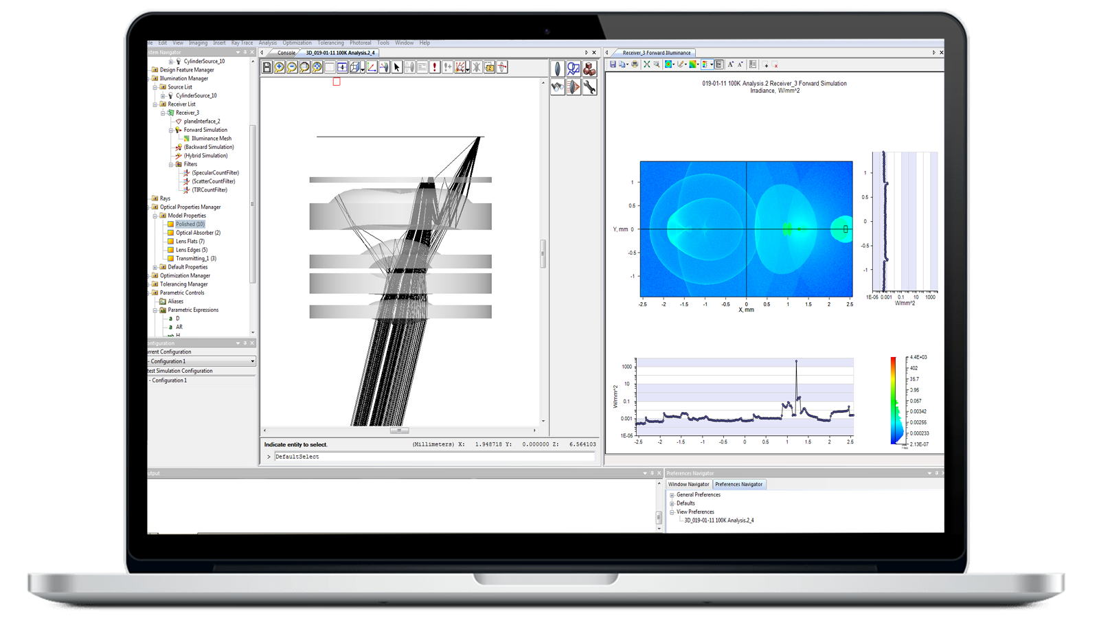
Software can help with almost all of these problems, although the designer remains essential in identifying problems and priorities. Even with all of this, it is still a challenge to turn it all to practice and produce lenses that meet all the requirements in actual use. Keysight offers several optical design engineering software solutions to help you achieve your objectives. Contact us to get help choosing which optical design software is best for your application.
Learn About Our Optical Design Software Tools




Learning More
There are some excellent sources of information about optics, most of them on paper in books and periodicals. This list is just a starting point — we will add to it over time and we welcome suggestions.
Basics
This site contains a lot of fascinating information on microscopy, from the basic optics of microscopes to advanced applications and sample images. It's worth a look for the excellent explanations, graphics, and some interactive Java tutorials on refraction, reflection, and other optical topics. It includes details on many subjects only briefly mentioned here, including diffraction, polarization, and interference. A fantastic web site!
- Eyewitness: Light by David Burnie (Dorling Kindersley, 1992)
Part of the Eyewitness Science Series, nominally for children, beautifully illustrated with excellent explanations.
- Optics by E. Hecht and A. Zajac (Addison-Wesley, 1974)
A good text at the undergraduate physics level.
Optical engineering and design
- Designing Optics Using CODE V® by Donald C. O'Shea, Julie L. Bentley
- Modern Optics Drawings: The ISO 10110 Companion by Eric Herman, David M. Aikens, Richard N. Youngworth
- Modeling The Imaging Chain of Digital Cameras by Robert D. Fiete
- Fabrication Methods for Precision Optics by Hank H. Karow
- A History of the Photographic Lens by Rudolph Kingslake
- Molded Optics: Design and Manufacture (Series in Optics and Optoelectronics) by Michael Schaub et al.
- Fundamental Optical Design by Michael J. KIdger
- Handbook of Optical Systems by Herbert Gross
- Aberrations of Optical Systems by W.T Welford
- Lens Design Fundamentals by Rudolf Kingslake, R. Barry Johnson (Academic Press, 2010)
Covers the fundamentals working designers need.
- Elements of Modern Optical Design by Donald O'Shea (Wiley-Interscience, 1985)
Excellent college-level text with good explanations and a practical orientation.
- Modern Optical Engineering by Warren Smith (Second Edition, McGraw-Hill, 1990)
The standard desk reference and learning tool for optical engineering.
Periodicals
- Optics and Photonics News (monthly, by subscription, Optica, Washington, DC)
News and technical articles (the monthly column "Light Touch" covers "everyday optics" for the non-professional).
Other resources
Visit this Canon website to see how a lens is made and how lenses function. Learn about different types of lenses (blue spectrum refractive optics lenses, fluorite lenses, EF lenses, and advanced lens coatings). Courtesy of Canon. They also have a science section for kids.
- The International Society for Optical Engineering (SPIE) and Optica (formerly OSA) are professional societies who maintain home pages with useful information and links to other organizations.
- Optics4birding.com is a site dedicated to bird watching, where quality optics are very important for viewing and photography. The “Learn About Optics” pages discuss a lot of basic optical concepts with a useful approach that is geared toward the importance of these concepts to the actual use of the optics.
- For more Keysight resources, please see our Optics for Kids educational content, resource page, and Pinterest board with educational material and projects.
Continued Learning


Want help or have questions?