How to Maximize Power Amplifier Efficiency and Linearity

Maximizing power amplifier efficiency and linearity with a VNA
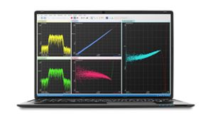
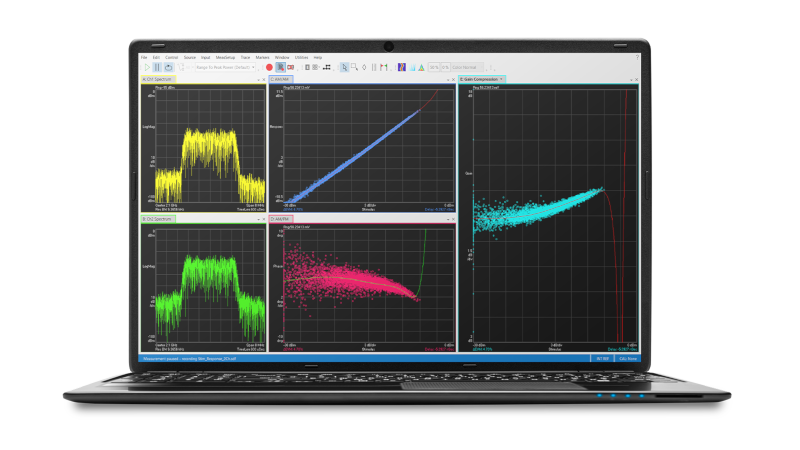
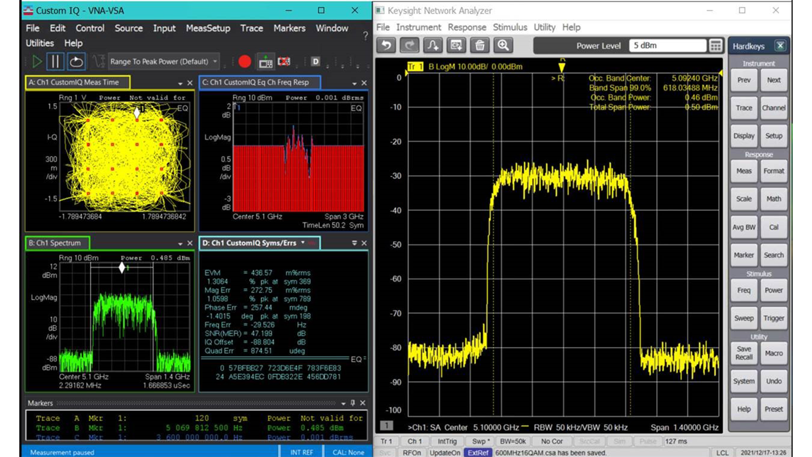
Maximizing power amplifier (PA) linearity, while maintaining efficiency, requires development of a digital predistortion (DPD) model. To provide optimal performance, the DPD technique needs wideband, calibrated vector signal generation and signal analysis.
Engineers use a vector signal generator and a vector network analyzer (VNA) with software-enabled wideband vector signal analysis capabilities to optimize PA efficiency and linearity on a single testbed. The VNA's multi-receiver architecture provides fully-calibrated signal generation at the PA input.
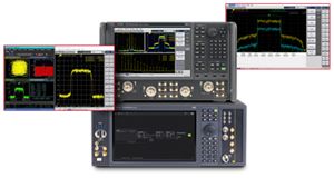

Power amplifier efficiency and linearity solution
See demo of power amplifier linearity test
Explore products in our PA efficiency and linearity solution
-

![]()
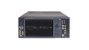
M9484C VXG Vector Signal Generator
-


![]()
S930705B Modulation Distortion up to 50 GHz
-
![]()
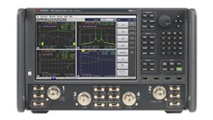
N5247B PNA-X Microwave Network Analyzer
-
![]()
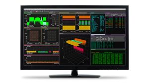
89601BHNC 89600 VSA 5G NR/5G-Advanced Modulation Analysis
-
![]()
89601200C 89600 Vector Signal Analysis Base Platform - Advanced Tier
-
![]()
S93051B IQ Data Bandwidth up to 4 GHz


Discover resources and insights
Additional resources for power amplifier efficiency and linearity
Related use cases

-
![]()
Learn More
How to Test 5G Protocol Conformance
Testing a 5G device for protocol conformance requires running GCF and PTCRB test cases. Learn how to test RedCap, NTN, USIM / USAT, IMS, LBS, LTE, NB-IoT, and C-V2X protocols with a protocol conformance toolset.
Learn more

-
![]()
Learn More
How to Measure the Energy Efficiency of an O-RU
Measuring the energy efficiency of an O-RAN radio unit (O-RU) requires an O-RAN distribution unit (O-DU) emulator, a DC power supply, and an RF power sensor. Learn how to measure energy efficiency following ETSI standards.
Learn more
-
![]()
Learn More
How to Test 5G Protocol Carrier Acceptance
Ensuring new 5G mobile devices comply with mobile network operators' (MNOs) infrastructure requires performing device acceptance testing. Learn how to verify the signaling between a mobile device and the network with multiple testing scenarios.
Learn more

Get in touch with one of our experts
Need help finding the right solution for you?