How to Verify Passive Component Quality

Verify Components Under Consistent Test Conditions
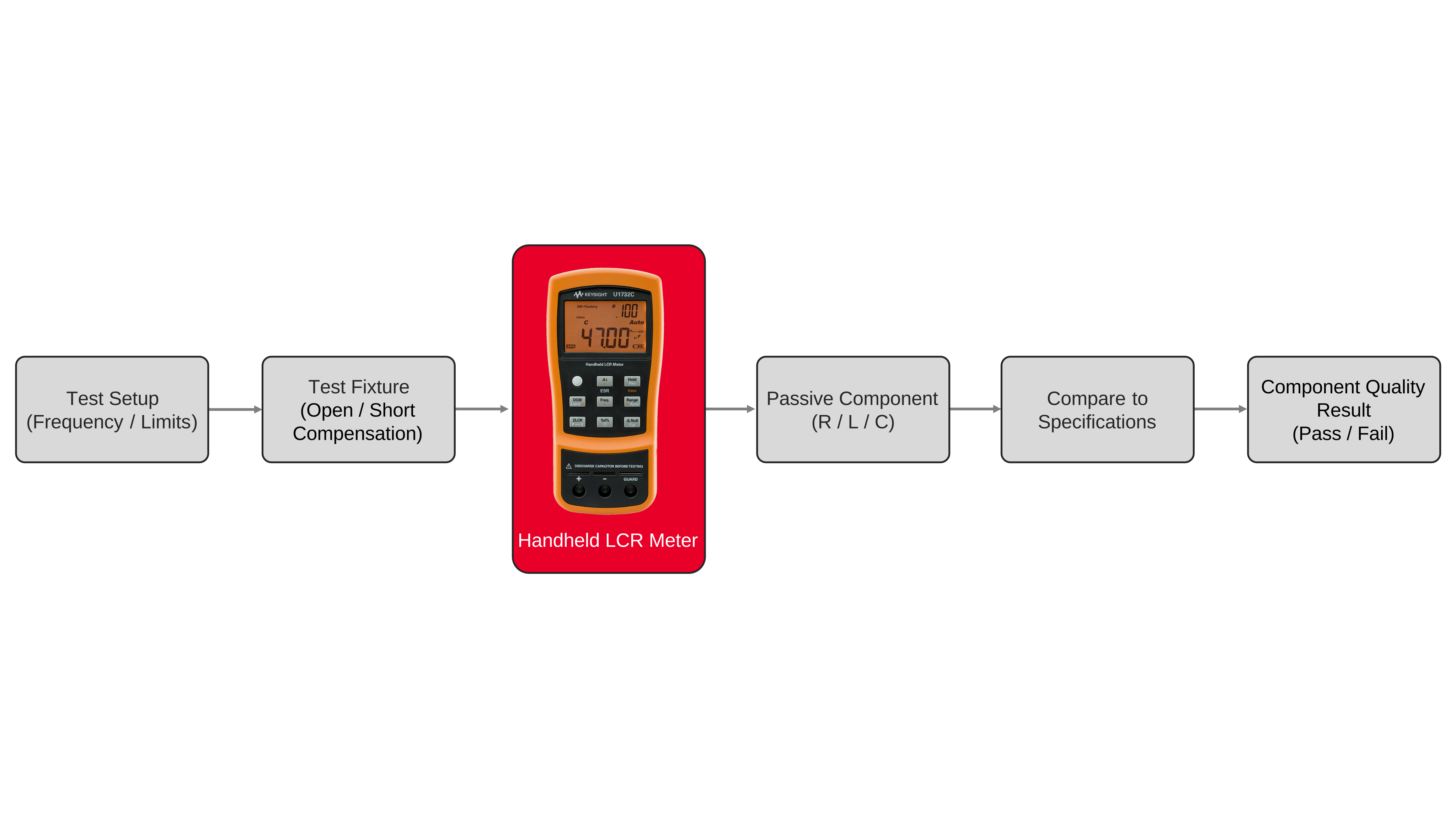
Passive component quality verification requires measuring resistance, capacitance, inductance, and related impedance parameters under controlled conditions and comparing the results with the expected electrical behavior of the component. The test requires an inductance, capacitance, and resistance (LCR) meter, an appropriate fixture or lead set, a defined test frequency, and acceptance criteria based on a component specification, reference sample, or internal test limit. Begin by identifying the primary parameter to verify and the conditions under which that parameter should be measured. Test frequency selection is part of the measurement because capacitive and inductive reactance change with frequency, and two components with the same nominal value can produce different results when measured under different electrical conditions. For resistance measurement, capacitance measurement, and inductance measurement, use the same frequency, equivalent-circuit selection, range, and fixture configuration when comparing multiple samples. An LCR meter can also provide secondary parameters such as impedance magnitude, phase angle, dissipation factor, quality factor, or equivalent series resistance. These values provide additional information when a component meets its nominal resistance, capacitance, or inductance value but behaves differently in a circuit. Incoming inspection can therefore combine a primary value check with one or more secondary impedance measurements that reflect the electrical characteristics relevant to the intended application. The measurement sequence should be defined before testing begins so that each sample is evaluated under the same conditions. A useful sequence is to configure the test frequency and measurement function, compensate the fixture or leads when required, connect the device under test, record the primary and secondary parameters, and compare the results with the specified limits. Keeping these conditions fixed supports passive component measurement that is repeatable across suppliers, production lots, or replacement parts and reduces the risk of interpreting setup variation as component variation.
Component verification also requires controlling the measurement interface and interpreting results in the context of actual operating conditions. Test leads, adapters, fixtures, contact resistance, stray capacitance, and residual inductance can influence the measured value, particularly when the component impedance is small or when the quantity being measured approaches the electrical contribution of the fixture itself. Use short, stable connections and a fixture appropriate to the component package, and perform the available open, short, or other compensation procedure using the same geometry that will be used for the samples. After compensation, avoid changing lead placement or fixture configuration between parts. For incoming inspection, measure a consistent set of samples using the same LCR meter settings and record both the nominal component parameter and any secondary parameter needed to distinguish electrical behavior. A capacitor comparison may include capacitance measurement together with equivalent series resistance or dissipation factor, while an inductor comparison may include inductance measurement with quality factor or phase information. A resistor may be checked with resistance measurement while monitoring impedance behavior if the application is frequency sensitive. Differences should be evaluated against the defined acceptance limits and the conditions under which the component will operate rather than against nominal value alone. When a substitute part from another supplier is being evaluated, repeat the same impedance measurement workflow for both parts so that the comparison is made under identical test conditions. The same approach can be applied when a component that passed development testing behaves differently during production: reproduce the original measurement conditions, compare primary and secondary parameters, and determine whether the observed difference is associated with the component or the test setup. This structured LCR meter workflow supports impedance measurement accuracy and consistent passive component measurement during incoming inspection, component comparison, troubleshooting, and bench verification while preserving the measurement conditions needed for meaningful sample-to-sample decisions.


Passive Component Quality Verification Solution
Block Diagram of Passive Component Quality Verification Solution

Explore Products in Our Passive Component Quality Verification Solution
-

![]()
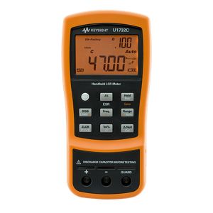
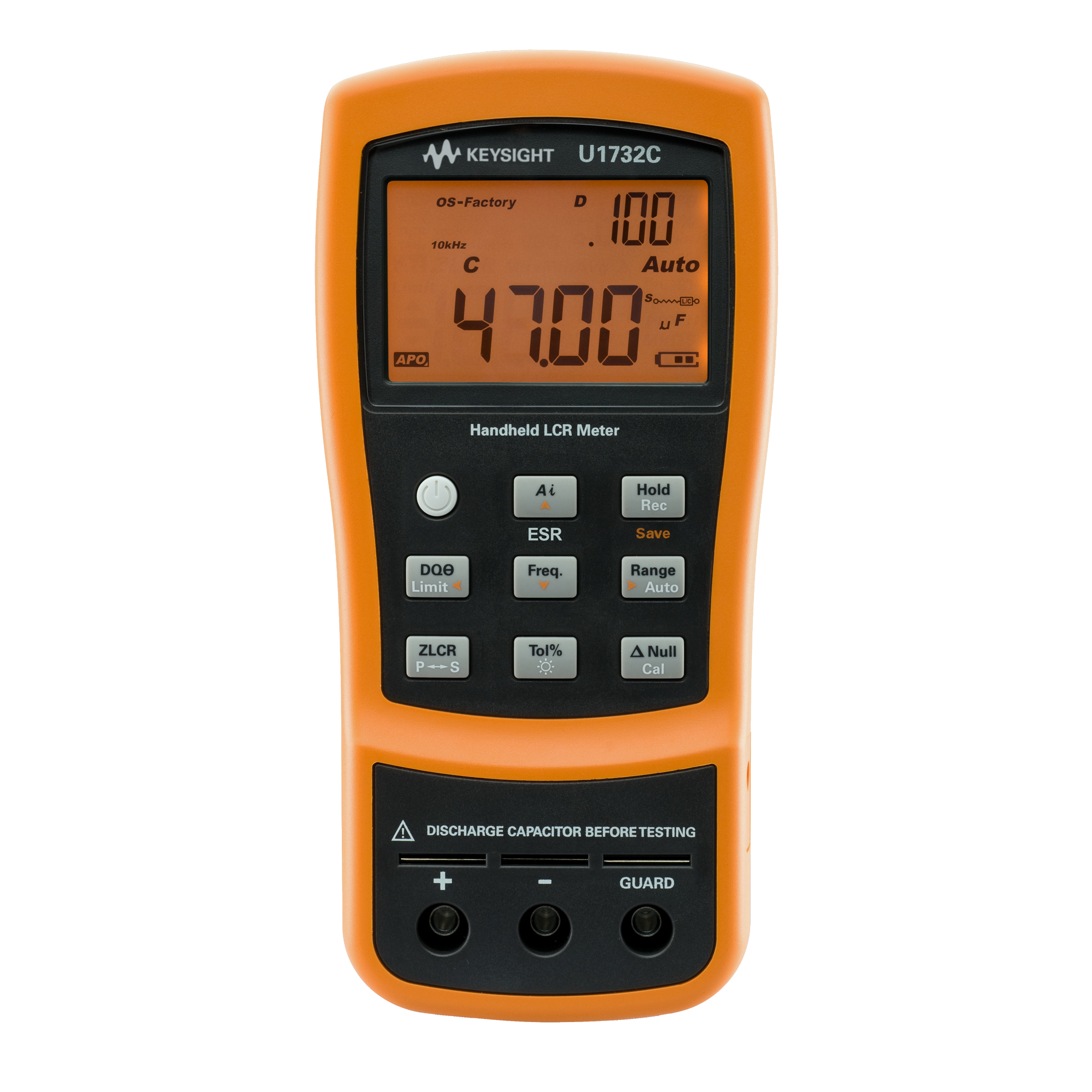
U1732C 100Hz / 120Hz / 1kHz / 10kHz Handheld LCR Meter

Discover Resources and Insights
Additional Resources for Passive Component Quality Verification
Related Use Cases


-
![]()
Learn More
How to Screen Capacitor Tolerance in Incoming Inspection
Screen capacitor tolerance during incoming inspection using precision capacitance measurements to ensure component quality and consistency with a capacitance meter.
Learn More

-
![]()
Learn More
How to Test PCIe 7.0 Transmitter Compliance
Learn how to test PCIe 7.0 transmitter compliance at 128 GT/s using PAM4 eye analysis, SNDR measurement, jitter decomposition, and automated validation workflows on high-bandwidth oscilloscopes.
Learn More
-
![]()
Learn More
How to Eliminate Thermal EMF Measurement Errors
Learn how to eliminate thermal EMF errors in low-resistance measurements using current reversal, applying forward and reverse current and averaging the voltages to cancel offset errors.
Learn More

Get in Touch with One of Our Experts
Need help finding the right solution for you?