Können wir Ihnen behilflich sein?
LightTools Illumination Design Software
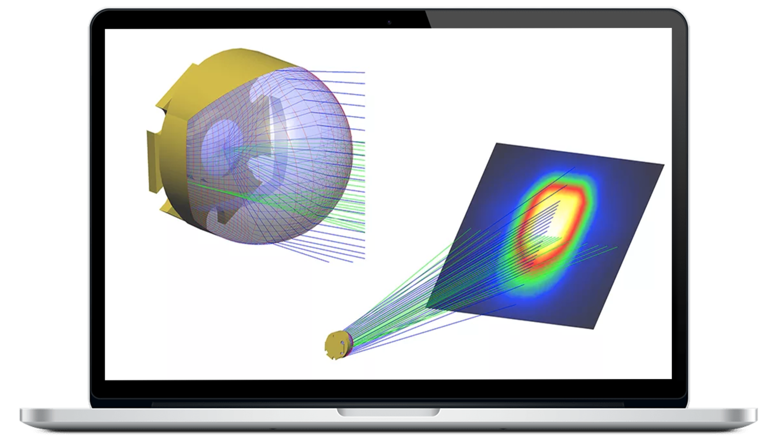
3D optical design software to create, analyze, and optimize illumination designs

Gain a Competitive Edge with LightTools Illumination Design
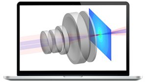
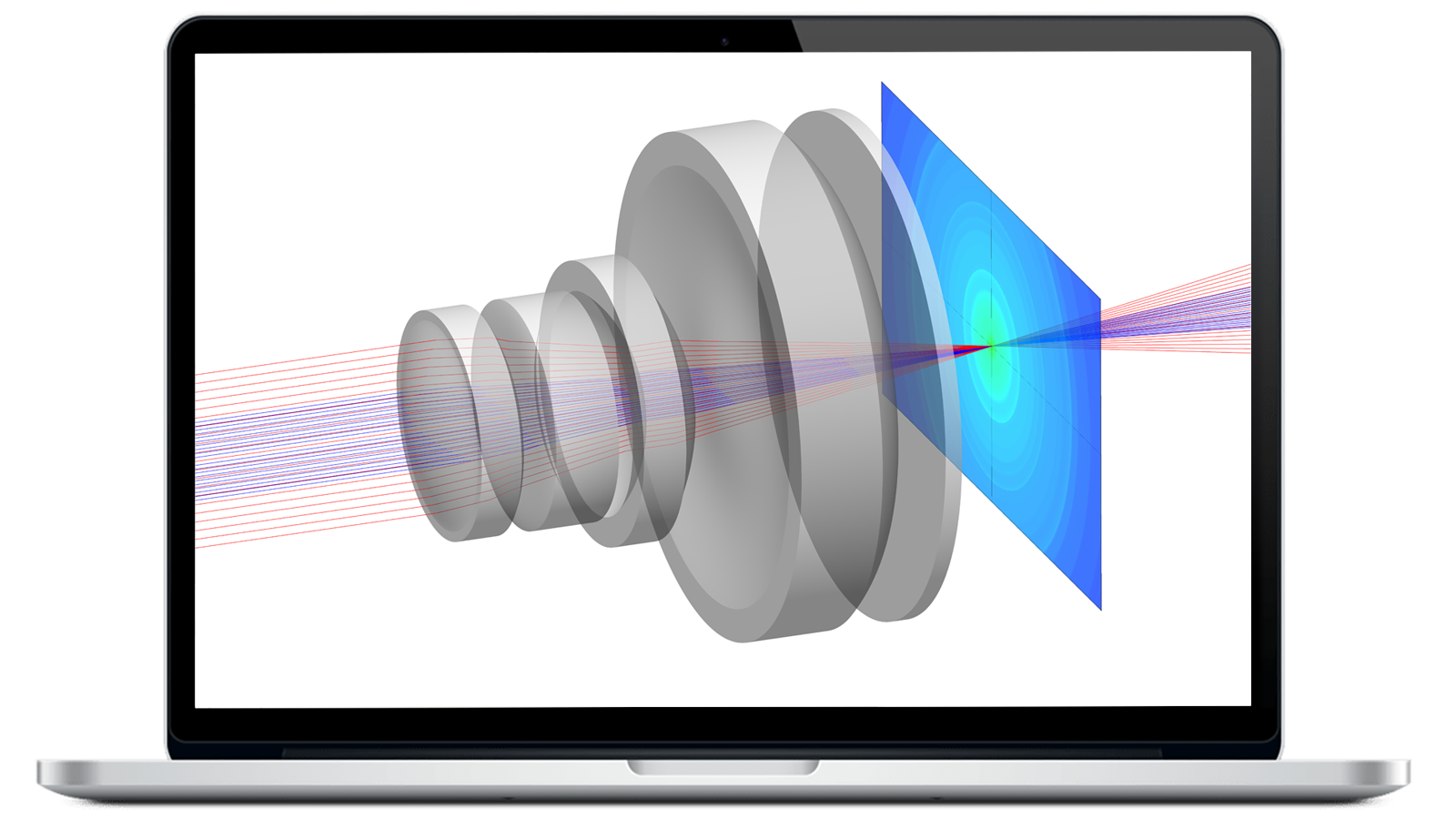
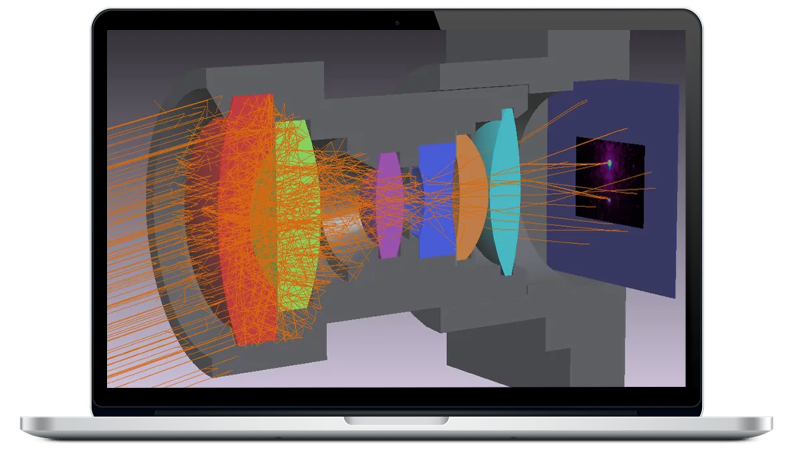
In competitive industries such as automotive, manufacturing, and consumer electronics, rapidly developing complex products with precision optics — such as light detection and ranging (LiDAR), liquid crystal displays (LCDs), and light-emitting diode (LED)-based systems — play a critical role in business success. With Keysight LightTools illumination design software, optical engineers can create virtual prototypes, simulations, and photorealistic renderings of complex illumination applications to delivery accurate, high-performance optical designs. LightTools can help you accelerate your time to market with an intelligent, easy-to-use solution.
- Ensure full-optical accuracy with advanced solid modeling and real-world simulation tools.
- Save time and money with actionable insights and analysis provided early in the design process.
- Speed design and development with LightTools’ intuitive user interface, extensive data library, and automated workflows.
- Improve efficiencies with a flexible optical design solution, configuring LightTools modules to best match your needs.
- Seamlessly integrate with CODE V for illumination, ghost image, and stray light analysis of imaging and non-imaging components.
Expanded Design and Analysis Capabilities
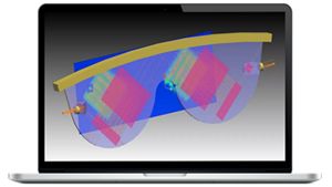
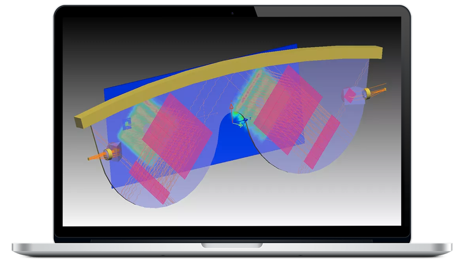
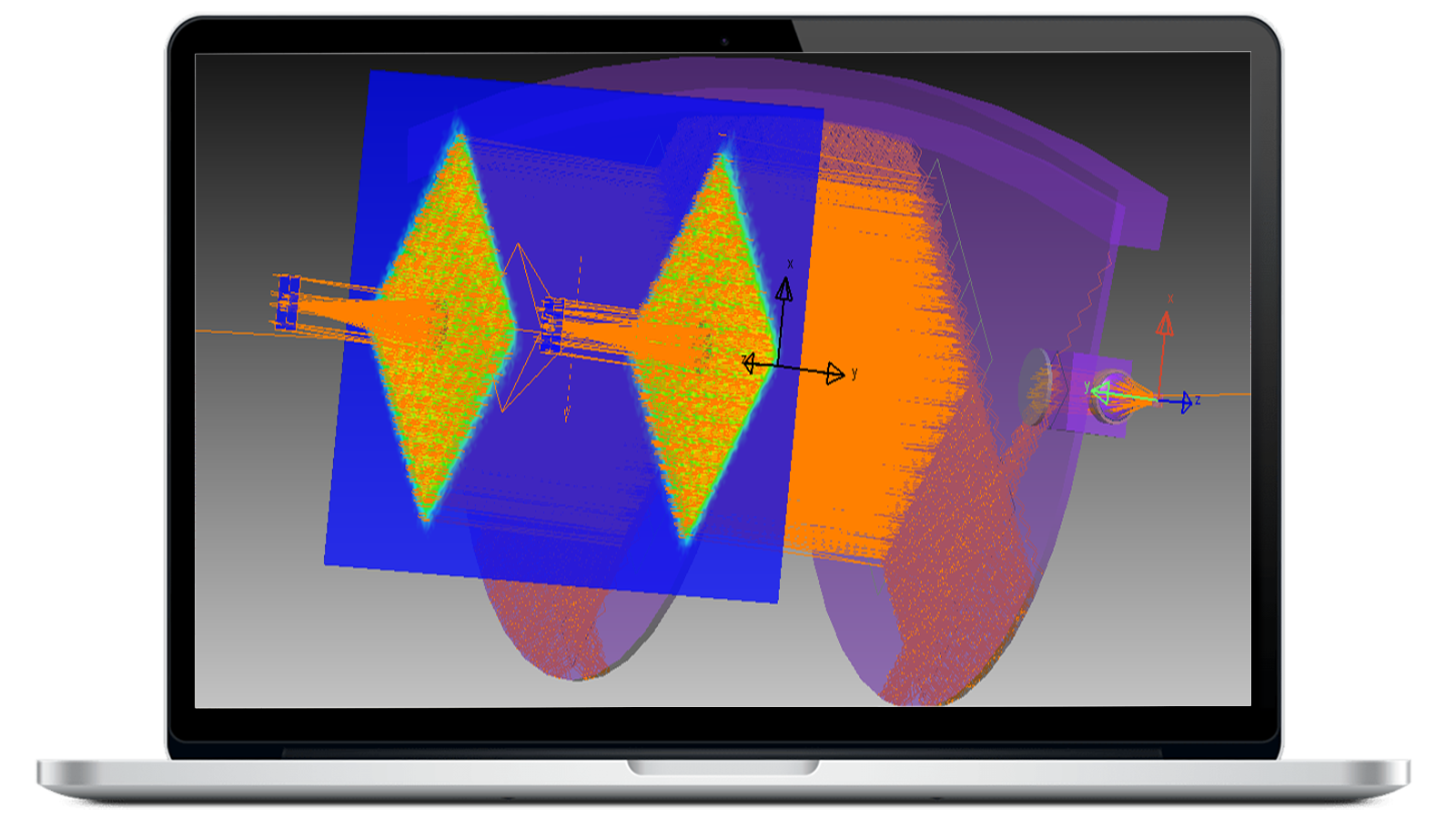
LightTools 2026 introduces new capabilities that help engineers visualize, simulate, and refine optical systems more efficiently. New features include VisionSym integration for photorealistic rendering, GPU-accelerated forward ray tracing, the AR Waveguide Designer for near-eye display applications, and support for meta-optic simulations. Additional workflow enhancements and expanded CAD interoperability provide greater flexibility throughout the design process.
Key Features of LightTools
Automatic system optimization
Automatic updates with new features and improvements make it easy to define your performance criteria and let LightTools find the best design solution.
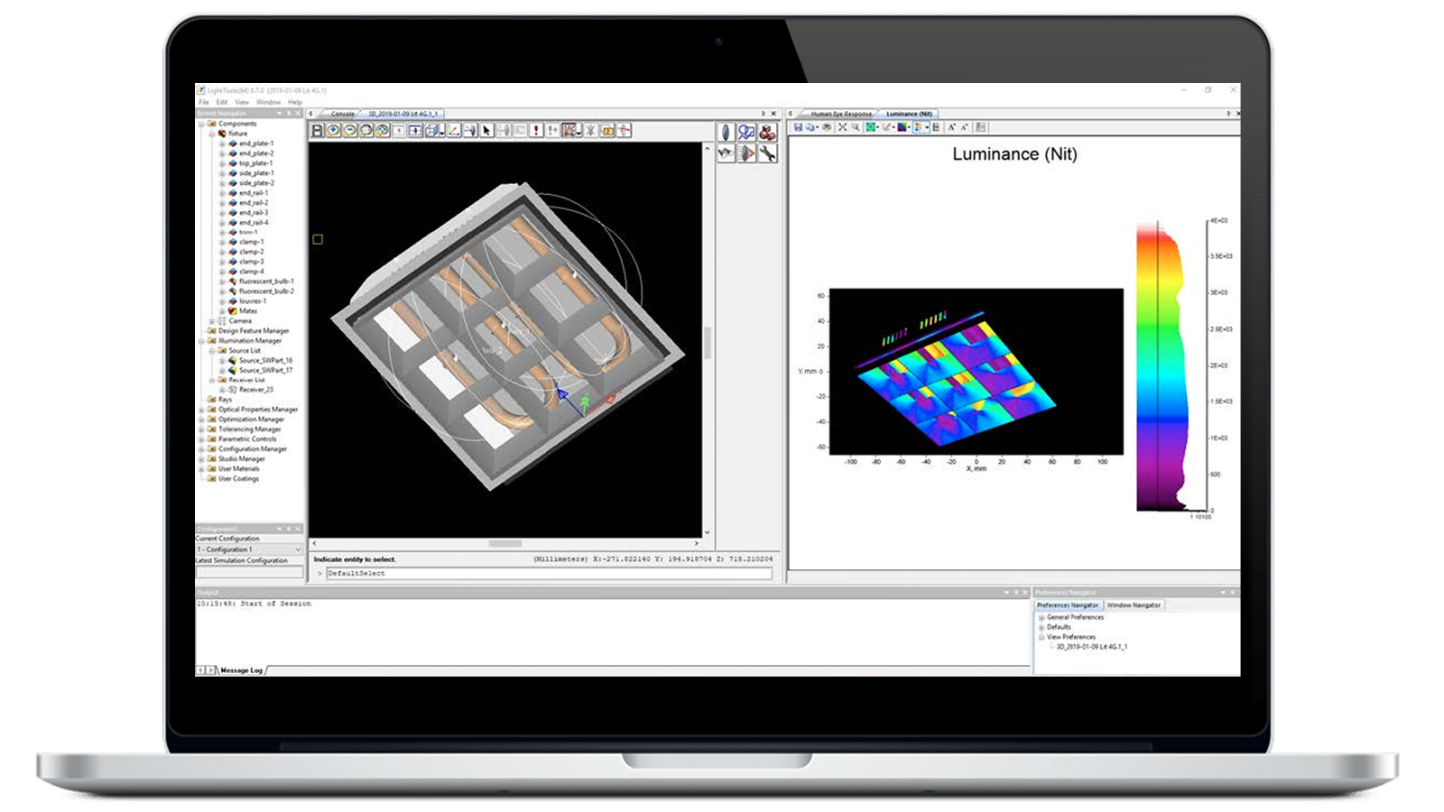
Easy design visualization
Focus on design, not setting up spreadsheets and complicated macros with LightTools’ intuitive, application-specific tools, reducing setup and analysis time.
Efficient modeling of complex shapes
Engineer solutions for getting light through a system and model unusual optical shapes or geometrically complex fixed portions of a design system.
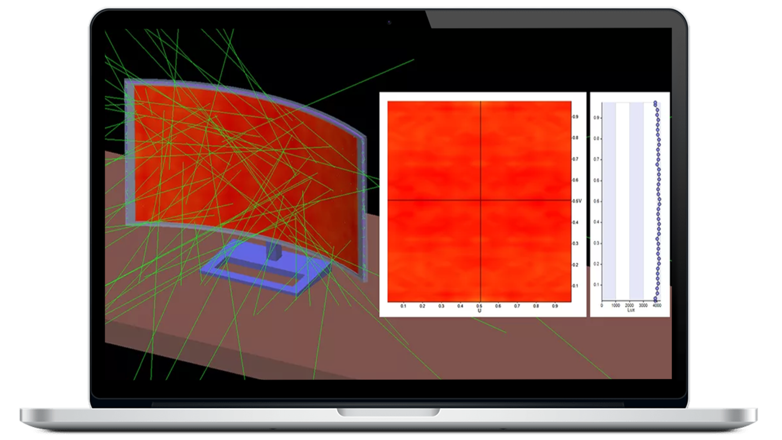
Real-world simulation
Visualize surface effects like polarization, scatter, and refraction, as well as material effects such as dispersion and color filtering.
Rich component library
LightTools’ customizable online library comprises a wide array of optical components, including lenses, mirrors, prisms, and diffractive elements.
Configure LightTools Modules to Best Meet Your Needs

Core Module
Create and visualize optical and opto-mechanical systems with the Core Module’s graphical 3D solid modeling functionality and libraries of task- and application specific utilities. Core Module is a prerequisite for additional modules.
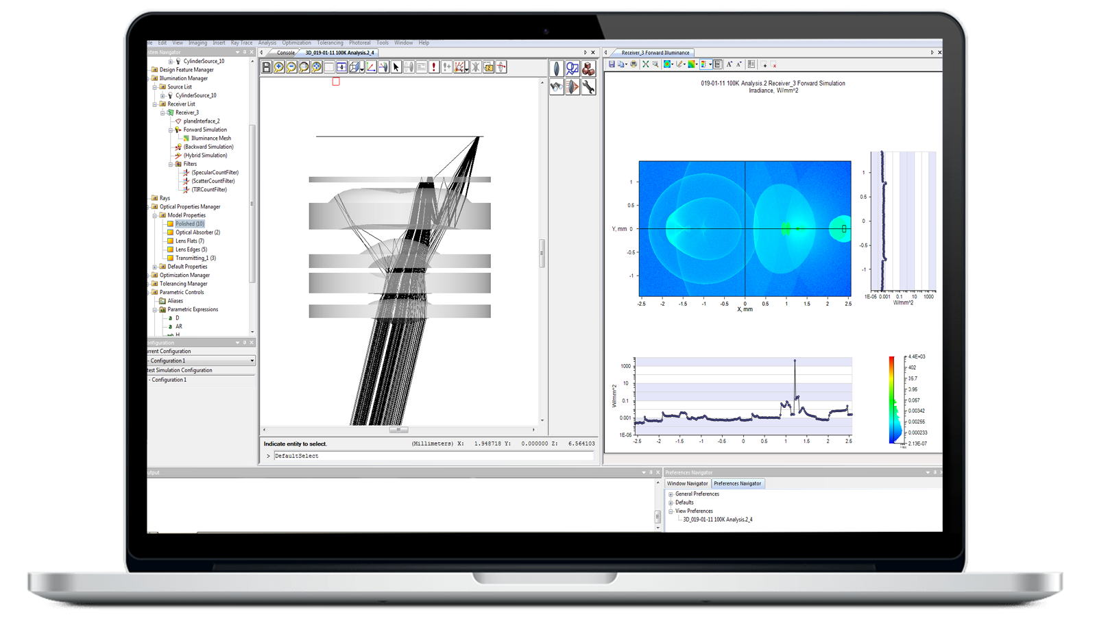
Illumination Module
Simulate and analyze light as it traverses the optical and mechanical components in a model. Get accurate predictions of intensity, luminance, and illuminance throughout the model with Monte Carlo ray tracing and analysis capabilities.
Optimization Module
Automatically improve the performance of your illumination system with the Optimization Module. Get practical, realistic solutions in a fraction of the time with integration in LightTools 3D solid modeling environment.
Advanced Design Module
Use the Advanced Design Module’s specialized tools to enable fast, robust modeling of reflective and refractive freeform optics in both single-surface and segmented configurations for a diverse set of illumination applications.

Advanced Physics Module
Extend optical modeling capabilities in LightTools for custom optical parts and advanced illumination subsystems. The Advanced Physics Module includes modeling of phosphors, user-defined optical properties, and gradient index materials.

SOLIDWORKS Link Module
Link SOLIDWORKS mechanical models to LightTools for an improved workflow, design accuracy, and efficient optomechanical modeling. Assign optical properties, optimize, and directly update your SOLIDWORKS design.

Data Exchange Module
With the Data Exchange Module, you can easily import complex geometries into LightTools and export industry-standard CAD file formats, including IGES, STEP, SAT, CATIA V4 and V5, and Parasolid formats.


LightTools SmartStart Library Module
Access a library of materials and media used in optical system design with the LightTools SmartStart Library Module. Get refractive index and absorption data plus pre-defined volume scatter and bi-directional scattering distribution function (BSDF) materials.
Imaging Path Module
Define an imaging path based on sequential optical surfaces and perform lens analyses — on image quality, aberrations, magnification, and more — with the Imaging Path Module. Use it directly in LightTools or in conjunction with CODE V.


Distributed Simulation Module
Use the Distributed Simulation Module to distribute large, computation-intensive Monte Carlo ray tracing over multiple computers to boost ray trace speed for stray light and luminance analyses and conduct forward and backward simulations.

LightTools MetaOptic Design
Accurately characterize gratings with RSoft Photonic Device Tools’ proprietary BSDF formulation in the MetaOptic Design Module. Save resources and reduce the complexity of setting up and analyzing an AR/VR system.

Imaging Analysis Module
Use the Imaging Analysis module to trace the rays that contribute to desired paths with surface sequences that follow a defined order, propagation direction, and type. Improve accuracy and reduce result computation time with sequence ray tracing.
Need Support for LightTools Products?
Explore Blogs


Featured Resources


LightTools Illumination Design Software – FAQ
LightTools Illumination Design software is a 3D optical engineering and design product that supports virtual prototyping, simulation, optimization, and photorealistic rendering of illumination applications.
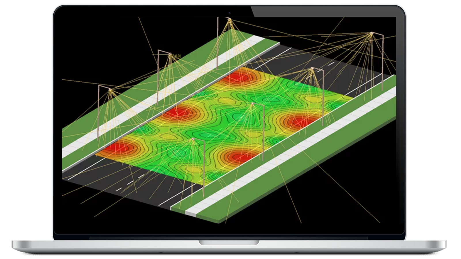
LightTools facilitates innovative designs for a broad range of solid-state lighting applications, including interior and exterior vehicle lighting, fiber light engines, complex light guides, projection systems, machine vision systems, solar collection systems, and more.
Optical system data
| Number of optical elements allowed | Unlimited |
| Number of wavelengths allowed | Unlimited |
| Linear dimension options | Inches, nm, mm, cm, meters |
| Macro language | Yes (model creation, manipulation, analysis) |
| Number of sources allowed (Illumination only) | Unlimited |
| Number of receivers allowed (Illumination only) | Unlimited |
| Number of imaging paths allowed | Unlimited |
| Number of fields (imaging paths only) | Unlimited |
| Pupil specification options (imaging paths only) |
|
| Field specification options (imaging paths only) |
|
| Reference rays (imaging paths only) | Chief ray plus unlimited reference ray definition (number and position) |
| Aperture stop (imaging paths only) | Definable on any optical surface |
| Automatic and user-defined data setting |
|
Optical elements
Surface shapes |
|
| Radius specifications | Radius or curvature |
| Radius type solves (imaging paths only) |
|
| Thickness solve types (imaging paths only) |
|
| Number of solves per element | 4 (2 radii and 2 thicknesses, imaging paths only) |
| Surface characteristics - refract mode (can be applied to any surface shape) |
|
| Surface Scattering | Lambertian, Gaussian, cosn, user-defined, mixed distributions, elliptical Gaussian (BSDF) |
| Volume Scattering | Mie, user-defined, or Henyey Greenstein |
| Importance Sampling | Yes, via aim area and/or aim sphere |
| Surface properties |
|
| Diffractive surface forms |
|
| Diffraction direction | Transmission, reflection, both (multiple orders allowed) |
| Glass types |
|
| Glass entry method | Info dialog box or via Glass Map |
| Glass catalogs supplied | Schott, Ohara, Hoya, Chance, Corning France, Kodak, Baush and Lomb, Corning, Special or user material |
| Aperture shapes allowed | Circular, Rectangular, Arcuate, Ellipse, or Bitmap |
| Number of apertures per surface | Unlimited |
| Aperture location | Arbitrary location and orientation on surface |
Optical element operations
| Stretch lens focal point (changes power) | Yes (front or back focal point) |
| Bend lens (maintains power) | Yes |
| Cement/Uncement two elements | Yes (cementing changes 2nd radius as necessary) |
| Immersion | Yes |
| Scale | Yes |
| Move | Yes (absolute or by vector) |
| Copy | Yes (absolute or by vector) |
| Rotate | Yes (absolute or in pane) |
| Array | Yes (rectangular or circular)
|
| Fold (maintains 2:1 ratio for old mirrors) | Yes (absolute or in pane)
|
| Group/Ungroup elements | Yes |
| Align to user-coordinate system | Yes (along any axis) |
| Delete/Undelete | Yes (unlimited)
|
Non-optical elements
| Number of non-optical objects allowed | Unlimited |
| 3D object primitives |
|
| 2D object types | Lines, Rectangles, Text |
Boolean operations
| Types of operations |
|
| Unbool operation | Yes, breaks apart into components
|
| Number of Boolean operations allowed | Unlimited |
| Editing | Yes, all Boolean operations can be edited without the need to re-perform the operation |
| Applicable objects | All 3D objects, optical or non-optical (except sources) |
Non-sequential ray tracing
| Ray tracing modes |
|
| Invoking procedure | Point-and-shoot (select type, starting point, and direction) |
| Automatic update | Yes, upon any optical system change |
| Physical representation | Exact replication of behavior in 3D space, including splitting, TIR, multiple-order diffraction, scattering, etc. |
| Visualization | Color, line width, line style, show/no show all user-selectable |
Views
| 3D View | Wireframe, translucent, solid
|
| 2D View | Planar, profile representation of 3D model |
| Table view | User-definable tables of components, sources, imaging paths, or non-sequential rays |
| Special purpose views |
|
| Number of open views allowed | Unlimited |
| Updating | Automatic updating of all open views |
| VRML Export | Yes |
Construction tools
| Layers | 32 maximum (user-defined layer names) |
| Grid |
|
| Grid snap (element positioning) |
|
| Coordinate system |
|
| Positioning |
|
Layout views
| Windowing |
|
| Layout panes (3D Design view) |
|
| Viewpoint default |
|
| Viewpoint modification (3D Design view only) |
|
| Visibility | On/Off by layer or entity type |
| Rendering resolution | Selectable by slider |
| Color |
|
Text annotation
| Text features |
|
| Ancillary elements | Lines, arrows (in library), boxes |
| Supplied fonts | 15 |
| Maximum number of fonts allowed | Unlimited
|
Illumination features (with Illumination Module only)
| Source properties |
|
| Point source angular distribution | Lambertian, Uniform, User-defined |
| Surface emitter angular distribution | Lambertian, Uniform, User-defined |
| Surface emitter spatial distribution | Uniform, user-defined |
| Volume emitter angular distribution | Uniform, user-defined |
| Volume emitter volume distribution | Uniform, cylinder, user-defined |
| Number of sources | Unlimited |
| Receivers |
|
| Number of receivers | Unlimited |
Ray trace |
|
Number of rays |
|
| Output |
|
| Analysis |
|
Standard interfaces
| Export |
|
| Import |
|
Optional import/export interfaces (with Data Exchange Modules)
| IGES |
|
| STEP | supports AP 203 CC 6 and AP 214 CC 2 |
| SAT | reads and writes versions 1.5, 2.0, 3.0, 4.0, 5.0 |
| CATIA | reads and writes CATIA V4 and V5 |
Imaging paths (with Imaging Path Module only)
| Number of imaging paths allowed | Unlimited
|
| Ray tracing types allowed | Sequential or non-sequential |
| Imaging path definition | By non-sequential ray By surface selection |
| Imaging path update | By adding objects or surfaces By non-sequential ray |
| Imaging Path view | Represents a single imaging path (includes lens prescription table with traditional sign conventions) |
| Field specification | Graphically via Field Spec window |
| Reference ray specification | Graphically via Pupil Map window |
| Optical performance plots | Ray aberration curves Spot diagrams |
| Exportable to CODE V | Yes |
| Importable from CODE V | Yes |