
Stray Light Analysis and Control in a Maksutov–Cassegrain Telescope: A Model-Based Workflow
Stray light is one of the most persistent challenges in optical system design. Whether you are building astronomical telescopes, satellite sensors, automotive cameras, or AR/VR displays, unwanted light can degrade image quality, reduce contrast, and compromise system performance.
This article explores a structured approach to stray light analysis and control using a Maksutov–Cassegrain telescope as a case study. We will walk through zero-order and first-order analysis, baffle optimization, and advanced scatter modeling—all within a model-based design workflow.

Model of a telescope in LightTools
Understanding Stray Light and Its Impact
Stray light refers to any unwanted light reaching the detector. It can originate from direct paths caused by insufficient baffling, scattered light from optical or mechanical surfaces, ghost reflections from lenses or mirrors, diffraction from apertures, or even thermal emission in infrared systems. These effects are not just theoretical—they have real-world consequences. For example:
- Spaceborne sensors must make precise radiometric measurements in the presence of solar glare.
- Astronomical telescopes need to observe faint objects near bright sources.
- Automotive vision systems must process scenes accurately despite headlight glare.
- AR/VR systems demand high contrast image projection, making stray light control essential.

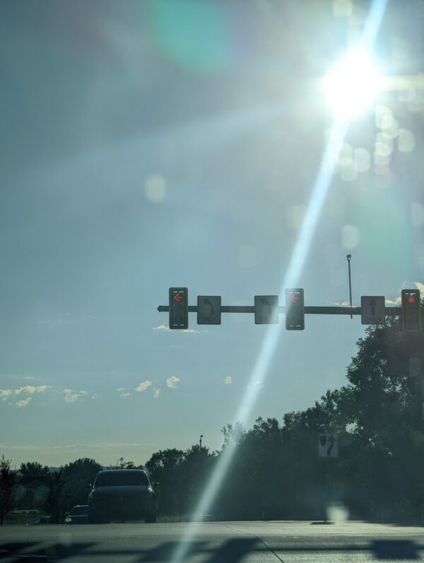
Example of stray light glare. Credit.
How Stray Light Is Analyzed
Modern stray light analysis requires specialized software capable of handling complex optical and mechanical models. This includes:
- Modeling multiple source types and complex geometries.
- Applying coating behavior as a function of angle of incidence, wavelength, and polarization.
- Performing non-sequential ray tracing with splitting and aiming.
- Modeling scatter using standard BSDF models or measured data.
- Computing radiometric quantities such as irradiance and intensity.
- Automating optimization loops for rapid iteration.
Without these capabilities, predicting and mitigating stray light effectively in high-performance systems is nearly impossible.

Using commercial simulation illumination design software, such as LightTools, for stray light analysis
Strategies for Controlling Stray Light
There are four primary strategies for controlling stray light1:
- Move It – Adjust geometry to eliminate problematic paths.
- Block It – Add baffles to intercept stray rays.
- Coat It – Apply absorptive or anti-reflective coatings to reduce reflections and scatter.
- Clean It – Maintain surface cleanliness to minimize contamination-induced scattering.
These strategies often work best in combination, depending on the system’s geometry and performance requirements.
Case Study: Maksutov–Cassegrain Telescope

Maksutov-Cassegrain Telescope modeled in CODE V

In order to perform the stray light analysis, the imaging design from CODE V is imported into LightTools.
Zero-Order Analysis: Mapping the FOV
Zero-order analysis focuses on identifying direct paths from external sources to the detector. To accomplish this, the detector is converted into an extended source, and rays are traced backward through the system. These rays are then binned by angular distribution to define the detector FOV in the system. Using the initial mechanical design provided, the resulting angular FOV is as shown below:

Note that there is a significant angular zone where light can reach the detector that does not follow the imaging path in the system. This is a zero-order stray light path.
Using the path analysis we can quickly identify that there is still a significant portion of the FOV that is directly visible to the detector even with the initial mechanical package design in place.

Zero-Order Ray Path Identification
Quantifying Stray Light: The SST Metric
To quantify the impact of stray light, we use the Stray Light Source Transmittance (SST) metric. This ratio compares the amount of stray light reaching the focal plane to the amount of light entering the system. For this analysis:
- The stray light source was modeled as an extended solar disk (80 mm radius, ±0.35° emission angle).
- Source power was normalized to provide 1 W/mm² irradiance at the detector plane when on-axis.
- SST values were calculated as a function of off-axis angle to evaluate system performance.

SST values for Initial Baffle Configuration
Baffle Design and Optimization
While the baseline baffle configuration reduced stray light, optimization delivered further improvements. Parameter sweeps were performed on the secondary baffle and main baffle opening to identify the most effective geometry. The revised design showed a significant reduction in SST compared to the baseline, demonstrating the value of iterative optimization in stray light control.

SST values for optimized baffle configuration
First-Order Analysis: Critical and Illuminated Objects
First-order paths involve a single scatter or reflection event. To identify these contributors, we classify objects as critical if they are visible to the detector and illuminated if they are lit by the external source. By combining forward and backward ray traces, we can find objects that meet both criteria. In our example, the interior barrel was illuminated at 5° off-axis and visible to the detector via the secondary mirror, making it a first-order contributor via scattering.

Identification of Critical and Illuminated Object for First Order Analysis
Modeling Surface Scatter
Accurate scatter modeling is essential for predicting first-order contributions. Software uses the Bidirectional Scatter Distribution Function (BSDF), which includes both BRDF (reflectance) and BTDF (transmittance) components. Common models include:
- Lambertian
- Gaussian
- Cos^N
- Harvey-Shack
- ABg
Scatter models can be isotropic or anisotropic and may be shift-invariant or non-shift-invariant. Measured data from instruments such as the Keysight REFLET 180S can also be incorporated for higher fidelity.
To accelerate convergence, scatter aiming techniques are employed. By generating aiming areas from a virtual detector image, simulations can focus rays on regions most likely to contribute to stray light. In our example case, using a virtual image of the detector improved hit rates by 45× and significantly reduced error estimates compared to aiming at the secondary mirror aperture.
First-Order Summary
In our example case using a highly reflective Lambertian scatter model, the barrel’s contribution from the 5°off axis stray light source was several orders of magnitude below the zero-order stray light and was determined not to be a concern for this system. Additional characterization across multiple angles is required to complete the analysis. If all sources of first-order stray light do not exceed allowable specifications, the analysis can be considered complete. Otherwise, additional mitigation steps such as specialized coatings or geometry changes may be required. Second-order analysis, involving two scatter events, is only necessary if first-order contributions were found to exceed stray light thresholds requirements for the overall system.
Conclusion
Stray light analysis is a multi-step process that requires careful modeling of geometry, coatings, and scatter. By combining zero-order FOV mapping, baffle optimization, and first-order scatter characterization, engineers can design robust optical systems that meet stringent performance requirements. Model-based workflows accelerate this process, enabling rapid iteration and data-driven decisions.
Resources to Learn More
- Fest, Eric C. Stray Light Analysis and Control. SPIE-International Society for Optical Engineering, 2013.
- Stover, John C. Optical Scattering Measurement and Analysis Third Edition. SPIE-International Society for Optical Engineering, 2012.
LightTools is celebrating its 31st anniversary—three decades of empowering engineers with advanced illumination and stray light analysis tools. Here’s to continued innovation in optical design!
Need Expert Optical Design Support?
Partner with our award-winning engineering team and bring your vision to life. Whether you need us to lead, assist, or advise, we’ll help you create a precise digital twin of your system—ensuring a seamless, on-time, and on-budget transition to hardware that works right the first time.
👉 Contact us today to integrate our experts into your next optical design project.