


-
Tisch-Gleichstromnetzteile
Mehrere sichere, saubere und zuverlässige Stromquellen erschließen


-
ATE-System-Netzteile
Beschleunigen Sie den Durchsatz in einer kompakten, rackmontierten Lösung
-
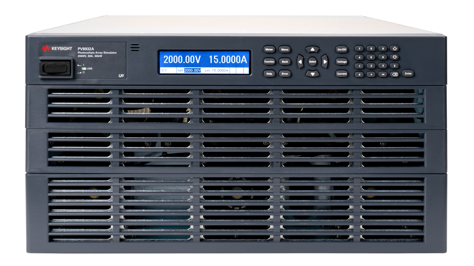
Speziallösungen für die Stromversorgung
Bewältigen Sie Energieprobleme mit anwendungsspezifischen Lösungen

-
Modulare Stromversorgungslösungen
Passen Sie Leistung und Leistungsaufnahme an Ihre Testanforderungen an.


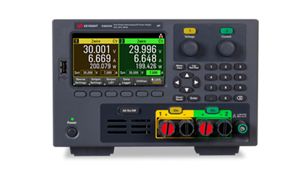
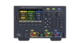
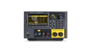
Tisch-Gleichstromnetzteile
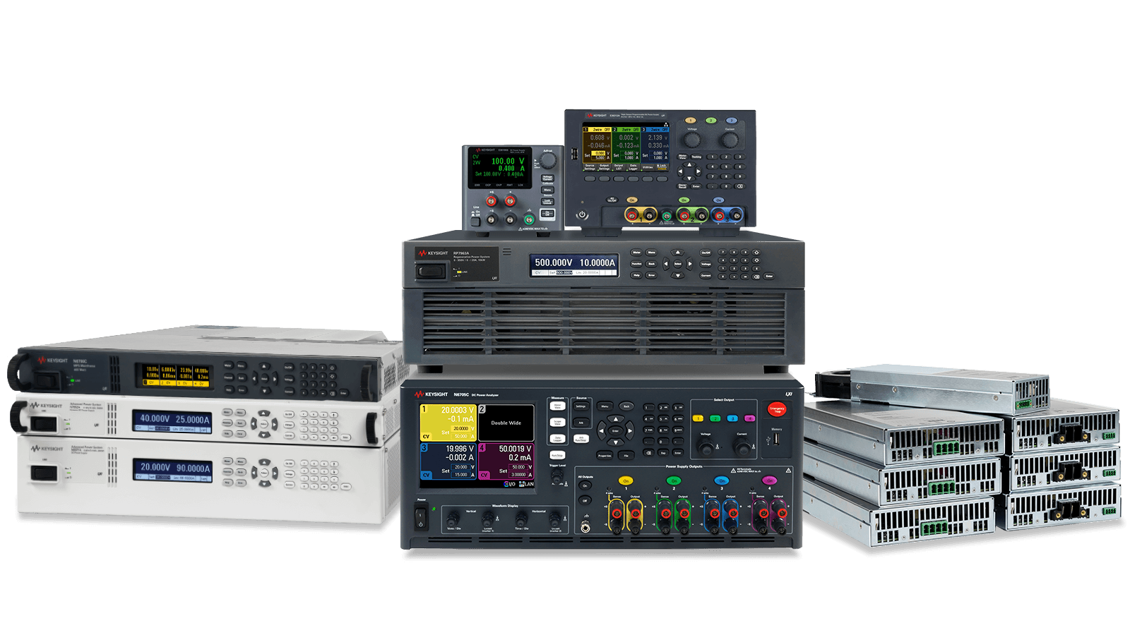
Keysight-Gleichstromnetzteile liefern stabile und präzise Stromversorgung für die Entwicklung, das Testen und die Validierung elektronischer Geräte in allen Phasen der Entwicklung und Produktion. Wählen Sie die Leistungsklasse, die Ihren Anforderungen entspricht – basierend auf maximaler Leistung, Spannung, Stromstärke und erweiterten Messmöglichkeiten. Entdecken Sie unser breites Portfolio an Gleichstromnetzteilen – von Essential bis hin zu Pro-Modellen – um das ideale Gleichstromnetzteil für Ihre Anwendung zu finden.


Essential

Advanced

Expert


Pro
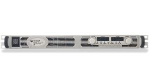
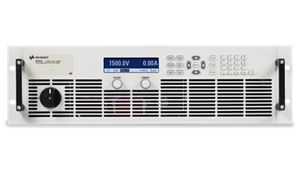
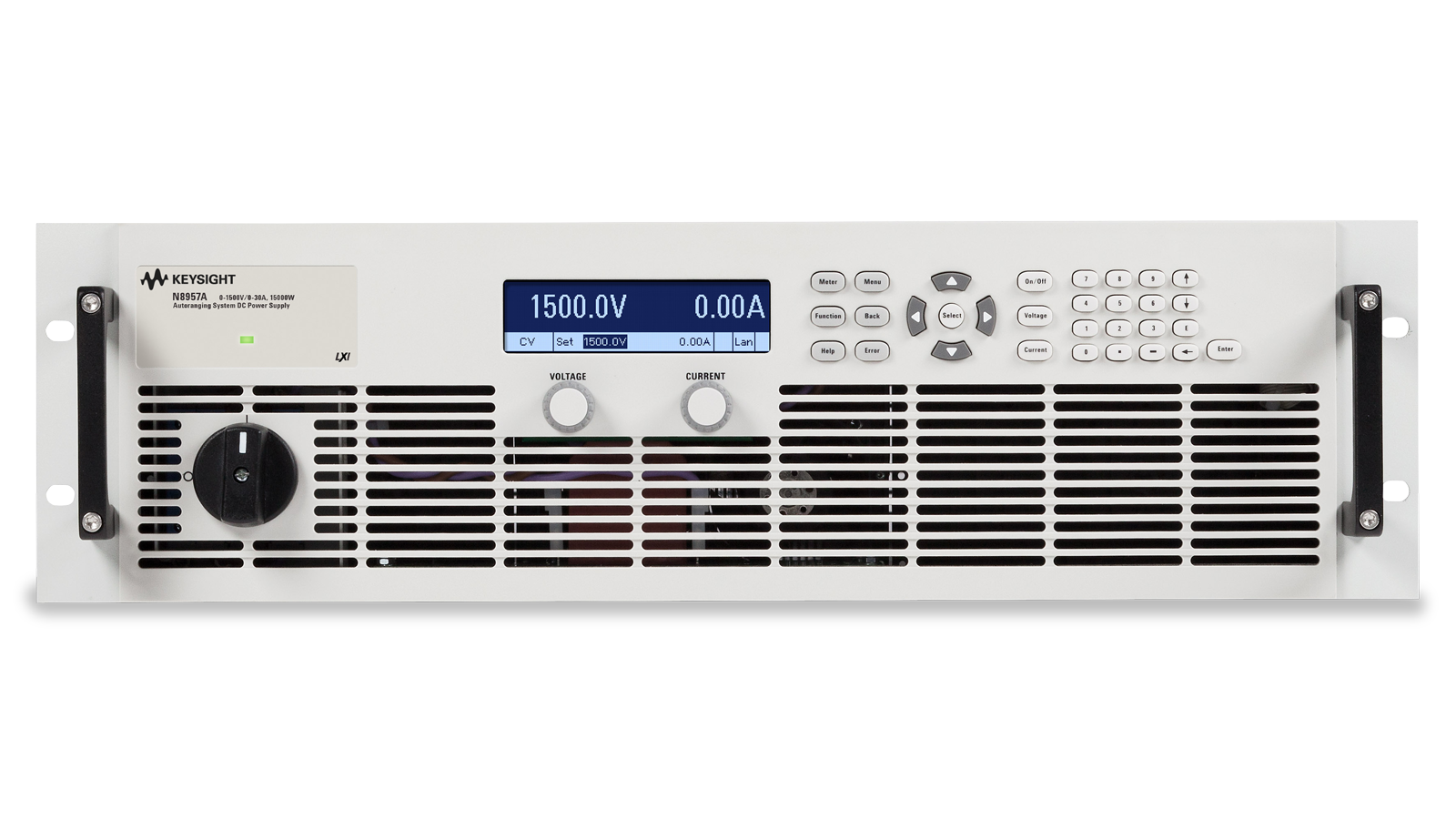
ATE-System-Netzteile
Keysight ATE-Systemnetzteile beschleunigen automatisierte Testabläufe durch schnelle Befehlsverarbeitung und kurze Einschwingzeiten und verkürzen so die Testdauer. Dank ihrer kompakten Bauweise mit hoher Leistungsdichte sparen sie wertvollen Rackplatz. Sie eignen sich ideal für schnelle Paralleltests und sind optimiert für Anwendungen in der Halbleiter-, Automobil-, Unterhaltungselektronik- und drahtlosen Kommunikationsindustrie – sowohl in der Produktion als auch in der Entwicklung. Entdecken Sie unser breites Sortiment an ATE-Systemnetzteilen. Advanced Um die richtige Leistungsbewertung für Ihre Anwendung zu finden, verwenden Sie die professionellen Leistungsklassen.
Advanced


Expert

Pro
Speziallösungen für die Stromversorgung
Die Speziallösungen von Keysight, darunter Batterieemulatoren, Photovoltaik-Simulatoren, Stromrichter für Hybrid- und Elektrofahrzeuge sowie Gleichstromquellen für die Mobilkommunikation, ermöglichen präzise Leistungssimulationen zum Testen energieintensiver Systeme. Mit diesen Lösungen können Sie kritische Komponenten in Elektrofahrzeugen, Systemen für erneuerbare Energien und Telekommunikationsanlagen unter realen Bedingungen validieren. Sie sind wichtig für Branchen wie die Automobilindustrie, die Erneuerbare-Energien-Branche und die Unterhaltungselektronik und gewährleisten zuverlässige Leistung und Konformität für Technologien der nächsten Generation. Entdecken Sie unser breites Angebot an Speziallösungen und finden Sie die passende für Ihre Anwendung.


Modulare Gleichstromversorgungslösungen
Die modularen Gleichstromversorgungslösungen von Keysight ermöglichen Ihnen die Optimierung von Leistung und Energieverbrauch für die jeweiligen Testanforderungen spezifischer Anwendungen. Wählen Sie Ihr Mainframe und aus über 35 Modulen – darunter Basis-, Hochleistungs-, Präzisions-, Source/Measure-Units (SMU) und elektronische Lasten – die passende Stromversorgungslösung für Ihre individuellen Anforderungen. Dank der vielfältigen Mainframes und Module finden Sie garantiert die modulare Gleichstromversorgungslösung, die optimal zu Ihrer Anwendung passt.


Lernen Sie unsere neuen Expert ATE-System-Netzteile
Die Weiterentwicklung von Hochleistungsinnovationen erfordert Testsysteme, die auf Präzision, Skalierbarkeit und Sicherheit ausgelegt sind. Keysight neue Expert Die Stromversorgungen von ATE System bieten alle drei Vorteile: regenerative Spannungsquellen der nächsten Generation, elektronische Lasten und eine für die Automatisierung geeignete Steuerungssoftware. Diese Lösungen wurden für missionskritische Validierungsanwendungen in der Luft- und Raumfahrt, der Energiespeicherung und in Rechenzentren entwickelt und ermöglichen schnellere, sicherere und energieeffizientere Tests. Dank branchenführender Genauigkeit und globaler Konformität können Sie Hochleistungsdesigns zuverlässig und kompromisslos validieren.
Finden Sie kompatible Software und Zubehör für Ihr Gleichstromnetzteil
Wählen Sie aus einer breiten Palette an Analyse-, Steuerungs- und anwendungsspezifischer Software oder Zubehör wie Kabeln, Modulen, Rack-Montagesätzen und mehr.
Anwendungsfälle von Gleichstromversorgungen erkunden
Gleichstromversorgungen unterstützen ein breites Anwendungsspektrum in verschiedenen Branchen – entdecken Sie sie alle.
Allgemeine Elektronik
Die Umgebungsbedingungen der Batterie und die Stromprofile des Geräts werden simuliert, um den Stromverbrauch zu analysieren.


Automobilindustrie
Validierung von EV-Leistungswandlerdesigns mit handelsüblichen Testressourcen.
%20front%20top.png "Validierung des Designs von EV-Stromrichtern")
 front top.png "Validierung des Designs von EV-Stromrichtern")
Automobilindustrie
Testen der Leistungsfähigkeit von elektronischen Steuergeräten (ECUs) in Kraftfahrzeugen unter verschiedenen Betriebsbedingungen.


Kabelgebundene Kommunikation
Führen Sie eine Einschaltsequenzierung durch, um die ordnungsgemäße Funktion und Sicherheit der Geräte zu gewährleisten.
Luft- und Raumfahrt und Verteidigung
Simulieren Sie mit einem Solaranlagensimulator alle IV-Kennlinien, die ein Satellit durchlaufen wird.


Dienstleistungen und Support
Innovieren Sie im Handumdrehen mit maßgeschneiderten Supportplänen und priorisierten Reaktions- und Bearbeitungszeiten.
Profitieren Sie von planbaren, leasingbasierten Abonnements und umfassenden Lifecycle-Management-Lösungen – damit Sie Ihre Geschäftsziele schneller erreichen.
Als KeysightCare-Abonnent profitieren Sie von einem erweiterten Service mit zuverlässiger technischer Unterstützung und vielem mehr.
Stellen Sie sicher, dass Ihr Testsystem den Spezifikationen entspricht und sowohl lokale als auch globale Standards erfüllt.
Schnelle Messungen dank hauseigener, von Ausbildern geleiteter Schulungen und E-Learning.
Laden Sie die Keysight-Software herunter oder aktualisieren Sie Ihre Software auf die neueste Version.
Häufig gestellte Fragen
Die Auswahl des richtigen Gleichstromnetzteils hängt von den Anforderungen Ihrer Anwendung ab:
- Anwendungsfall : Tischnetzteile eignen sich ideal für Labortests mit Bedienelementen an der Vorderseite und großen Displays. ATE-Systemnetzteile sind für automatisierte Testgeräte und die Rackintegration konzipiert.
- Leistungsanforderungen: Stellen Sie sicher, dass das Netzteil Ihren Spannungs- und Strombedarf deckt. Keysight Technologies bietet Modelle mit niedriger, mittlerer und hoher Leistung von wenigen Watt bis zu mehreren hundert Kilowatt an.
- Rauschen und Restwelligkeit: Empfindliche Anwendungen, wie z. B. Audiogeräte, benötigen rauscharme Stromquellen.
- Genauigkeit und Reaktionszeit: Überprüfen Sie, ob die Befehlsverarbeitungszeit und die Ausgabereaktion Ihrer Testgeschwindigkeit entsprechen.
- Mehrfachausgangs- oder Moduloptionen: Wenn mehrere Spannungsschienen benötigt werden, sollten Sie ein Mehrfachausgangs- oder Modulnetzteil für die Sequenzierung und Flexibilität in Betracht ziehen.
Bei der Auswahl eines Gleichstromnetzteils sollten Sie Spezifikationen wählen, die zu Ihrem Prüfling (DUT) und den Anwendungsanforderungen passen.
Wichtige Bewertungskriterien:
- Spannungsbereich (V) : Muss den Betriebsspannungsbereich des Prüflings abdecken (z. B. 0–30 V für Labortests, höher für ATE-Systeme).
- Strombelastbarkeit (A) : Stellen Sie sicher, dass für Spitzenlastbedingungen ausreichend Strom vorhanden ist (z. B. 3 A, 10 A oder höher).
- Nennleistung (W): Definiert die gesamte Ausgangsleistung (Leistung = Spannung × Stromstärke).
- Output Noise & Ripple: Critical for low-noise testing (e.g., <1 mVrms for sensitive analog/RF circuits).
- Load & Line Regulation: Indicates output stability under changing load or input conditions (e.g., <0.01%).
- Programmierung & Genauigkeit : Eine hohe Auflösung (z. B. mV/mA-Werte) verbessert die Testgenauigkeit.
- Transient Response: Fast response (<50 µs typical) for dynamic load testing.
- Bauform : Tischnetzteile für den Laboreinsatz vs. modulare/ATE-Systeme für automatisierte Tests.
- Anschlüsse : LAN, USB, GPIB für programmierbare Gleichstromversorgungssteuerung.
Die Gleichstromnetzteile von Keysight Technologies bieten hohe Genauigkeit, geringes Rauschen und programmierbare Steuerung sowohl für Labor- als auch für automatisierte Testumgebungen.
Gleichstromnetzteile ermöglichen eine präzise Spannungs- und Stromregelung durch die Bereitstellung einer stabilen, einstellbaren Leistung zum Testen von Schaltungen, Bauteilen und Systemen. Diese präzise Regelung ist unerlässlich für genaue und reproduzierbare Messungen in Anwendungen wie Prototyping, Fehlersuche und Produktionstests.
Unterschiedliche Gleichstromnetzteile unterstützen verschiedene Komplexitätsgrade von Tests. Gemeinsam ermöglichen diese Gleichstromnetzteile Ingenieuren, die passende Leistung, Stromstärke und Steuerung für die jeweilige Anwendung zu ermitteln. Von einfachen Labortests bis hin zu spezialisierten Hochleistungsmessungen gewährleisten Gleichstromnetzteile eine saubere, stabile und präzise Stromversorgung in unterschiedlichsten Testumgebungen.
Durch den Anschluss mehrerer Gleichstromnetzteile lässt sich die Spannungs- oder Stromstärke erweitern; dies wird häufig in ATE-Systemen und bei Hochleistungstests eingesetzt.
Reihenschaltung (Spannungserhöhung):
- Verbinden Sie den Pluspol der einen Stromversorgung mit dem Minuspol der anderen.
- Gesamtspannung = Summe der Einzelspannungen
- Beispiel: 2 × 30 V → 60 V Ausgang.
- Der Strom bleibt derselbe wie bei einer einzelnen Einheit.
Parallelschaltung (Stromstärke erhöhen):
- Verbinden Sie alle Pluspole miteinander und alle Minuspole miteinander.
- Gesamtstrom = Summe der Einzelversorgungen
- Beispiel: 2 × 5 A → 10 A Ausgang.
- Die Spannung bleibt konstant.
Bewährte Verfahren:
- Verwenden Sie aufeinander abgestimmte programmierbare Gleichstromnetzteile (z. B. von Keysight Technologies).
- Stellen Sie sicher, dass die Stromverteilung im Parallelbetrieb erfolgt (einige Netzteile unterstützen die automatische Lastverteilung).
- Überprüfen Sie die Isolationswerte vor dem Serienbetrieb
- Verwenden Sie geeignete Kabel, um den Spannungsabfall zu minimieren.
Modulare und parallelfähige Netzteile vereinfachen die Skalierung für Anwendungen mit höherer Leistung.
Beim Testen eines Netzteils ist Vorsicht geboten. Im Folgenden finden Sie Sicherheitshinweise für die Prüfung eines Gleichstromnetzteils. Wenn Sie mit Elektroniktests nicht vertraut sind, empfiehlt es sich, einen Fachmann zu konsultieren oder vorgefertigte Testgeräte zu verwenden.
- Beim Umgang mit Netzteilen müssen die entsprechenden Sicherheitsvorkehrungen getroffen werden, um Unfälle, Geräteschäden oder Verletzungen zu vermeiden. Eine der wichtigsten Maßnahmen ist, sicherzustellen, dass das Netzteil vor jeglichen Verbindungen oder Trennungen ausgeschaltet ist, insbesondere beim Anschließen oder Abziehen des Multimeters oder der Last. Die Handhabung des eingeschalteten Netzteils kann zu Kurzschlüssen, Stromschlägen oder Schäden am Messgerät führen.
- Netzteile sind unverzichtbare Komponenten in elektrischen und elektronischen Systemen und versorgen Schaltkreise und Geräte mit Energie. Jedes Netzteil hat jedoch definierte Grenzwerte für Spannung und Stromstärke. Eine Überschreitung dieser Grenzwerte kann schwerwiegende Folgen haben. Überschreiten Sie niemals die Nennspannung oder Nennstromstärke des Netzteils. Jedes Netzteil ist so ausgelegt, dass es eine maximale sichere Spannung und Stromstärke liefert. Eine Überschreitung dieser Grenzwerte kann zu Überhitzung, Bauteilausfällen oder sogar zu dauerhaften Schäden am Netzteil führen. Beachten Sie stets die Herstellerangaben und stellen Sie sicher, dass Ihre Last innerhalb der sicheren Betriebsgrenzen bleibt.
- Das Kurzschließen der Ausgangsklemmen eines Netzteils ist eine der gefährlichsten Handlungen beim Umgang mit elektronischen Geräten. Es kann zu unmittelbaren und schwerwiegenden Folgen führen, darunter Schäden am Netzteil, Verletzungen des Benutzers sowie Brand- oder Stromschlaggefahr. Vermeiden Sie unbedingt Kurzschlüsse an den Ausgangsklemmen. Ein direkter Kurzschluss am Ausgang eines Netzteils kann sofortige Schäden verursachen und interne Bauteile wie Sicherungen, Transistoren oder Kondensatoren beschädigen. Dies kann zu Funkenbildung, Hitzeentwicklung oder in schweren Fällen sogar zu Bränden führen. Gehen Sie beim Umgang mit den Anschlüssen stets vorsichtig vor, um versehentliche Kurzschlüsse zu verhindern.
Ein programmierbares Gleichstromnetzteil ist ein Präzisionsmessgerät, das einen hochstabilen und präzise geregelten Gleichstrom (DC) für ein Prüfobjekt (DUT) bereitstellt. Im Gegensatz zu einem einfachen manuellen Netzteil ermöglicht ein programmierbares Gerät die digitale Steuerung, Sequenzierung und Automatisierung von Spannungs- und Stromausgängen. Diese Funktionalität ist grundlegend für die moderne Elektronikentwicklung und ermöglicht die präzise Charakterisierung von Bauteilen sowie die nahtlose Integration in automatisierte Testsysteme (ATE).
Ingenieure in der Halbleiter-, Automobil- und Luftfahrtindustrie nutzen programmierbare Gleichstromnetzteile, um komplexe Konstruktions- und Fertigungsherausforderungen zu bewältigen:
- Designvalidierung und Margenprüfung: Durch programmatische Variation der Spannungs- und Strompegel werden die Betriebsgrenzen und die Effizienz der Komponenten ermittelt, um sicherzustellen, dass sie auch unter ungünstigsten Bedingungen zuverlässig funktionieren.
- Simulation von transienten Ereignissen in realen Umgebungen: Komplexe Stromstörungen wie Anlassvorgänge von Kraftfahrzeugen oder Spannungsabfälle werden nachgebildet, um zu überprüfen, wie ein Gerät auf schwankende, reale Strombedingungen reagiert.
- Stromversorgungsintegrität für Hochgeschwindigkeits-Digitaltechnik: Bereitstellung der extrem sauberen, rauscharmen Stromversorgung, die zur Validierung von Hochgeschwindigkeits-Digitalstandards (wie PCIe 5.0 oder DDR5) erforderlich ist, bei denen selbst geringfügige Spannungsschwankungen die Signalintegrität beeinträchtigen können.
- Batteriesimulation und -profilierung: Simulation des dynamischen Innenwiderstands und der Entladekurven spezifischer Batterietechnologien. Dies ist entscheidend für die Optimierung des Stromverbrauchs in IoT-Geräten, Wearables und Elektrofahrzeugen.
- Hochdurchsatzfertigung: Bereitstellung einer kontinuierlichen, zuverlässigen Stromversorgung für Burn-in- und Lebenszyklustests, um frühzeitige Ausfälle zu erkennen und die langfristige Produktzuverlässigkeit vor der Auslieferung sicherzustellen.
Der Hauptvorteil eines programmierbaren Gleichstromnetzteils liegt in der präzisen und steuerbaren Bereitstellung von Gleichspannung und -strom für reproduzierbare Tests. Im Gegensatz zu einer herkömmlichen Stromquelle ermöglicht ein programmierbares Gleichstromnetzteil die Einstellung von Ausgangswerten, Stromgrenzen und Betriebsmodi wie Konstantspannung und Konstantstrom, um die Anforderungen des Prüflings (DUT) zu erfüllen.
Im Bereich Test und Messung verbessert dies die Genauigkeit, schützt empfindliche Bauteile und erleichtert die Reproduktion identischer Testbedingungen von der Entwicklung und Fehlersuche über die Validierung bis hin zur Produktion. Ein programmierbares Gleichstromnetzteil unterstützt zudem automatisierte Tests über Fernschnittstellen wie USB, LAN oder optional GPIB, wodurch der manuelle Einrichtungsaufwand reduziert und die Workflow-Effizienz gesteigert wird. Je nach Modell stehen zusätzliche Funktionen wie Fernmessung, Datenprotokollierung, LIST-Modus, Ausgabesequenzierung und eine einstellbare Anstiegsgeschwindigkeit für komplexere Anwendungen zur Verfügung.
Der Hauptunterschied zwischen linearen und Schaltnetzteilen liegt im Verhältnis von Wirkungsgrad zu Rauschverhalten.
Lineare Gleichstromnetzteile:
- Bietet extrem geringes Rauschen und minimale Restwelligkeit (ideal für empfindliche Messungen).
- Hervorragend geeignet für analoge, HF- und Präzisionsprüfungen
- Geringere Effizienz → höhere Wärmeerzeugung
- Typischerweise verwendet in Labornetzteilen
Schaltnetzteile (Gleichstrom):
- Hoher Wirkungsgrad (oft >85–90%).
- Kompaktes und leichtes Design.
- Höheres Rauschen und stärkere Restwelligkeit im Vergleich zu linearen Netzteilen.
- Ideal für Hochleistungsanwendungen und ATE-Systeme.
Welches sollten Sie verwenden?
- Verwenden Sie lineare Netzteile für Anwendungen mit geringen Rauschanforderungen (z. B. Sensoren, HF-Anwendungen, Präzisionselektronik).
- Für hohe Leistung, Effizienz und automatisierte Tests sollten Schaltnetzteile verwendet werden.
Keysight Technologies bietet sowohl rauscharme lineare Tischnetzteile als auch hocheffiziente programmierbare Gleichstromnetzteile für skalierbare Testlösungen an.