How to Debug CAN FD and CAN XL Signals

Analyze CAN FD and CAN XL Communication
Controller Area Network Flexible Data-Rate (CAN FD) extends traditional Controller Area Network (CAN) communication with higher data rates and payloads up to 64 bytes, while Controller Area Network eXtra Long (CAN XL) further expands data capacity with payloads up to 2,048 bytes and higher-speed transmission. Both protocols retain arbitration mechanisms while allowing faster data transmission, creating different timing and physical-layer measurement requirements within a single frame. CAN FD debugging involves examining communication across arbitration and data phases, while CAN XL introduces additional frame structures and operating modes that support larger data transfers. Engineers need to determine whether unexpected communication behavior is associated with protocol activity or the underlying differential signal. CAN protocol analysis provides visibility into decoded messages and their corresponding electrical waveforms, helping engineers investigate timing and communication issues across these higher-capacity automotive networks.
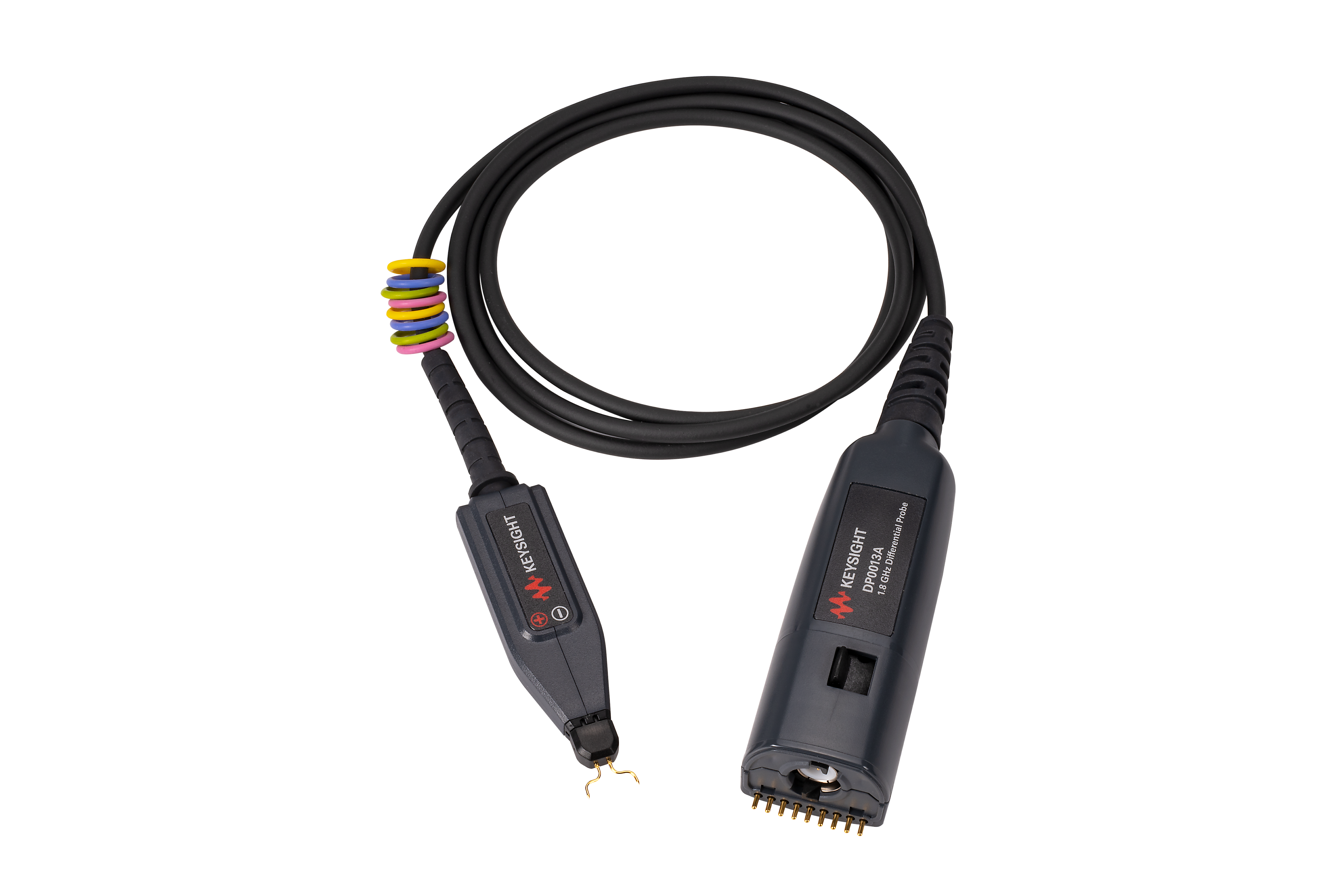
Performing the test requires an oscilloscope capable of acquiring differential CAN signals while triggering on and decoding CAN FD and CAN XL protocol activity. Engineers connect the oscilloscope across the bus using a differential active probe and configure the appropriate protocol settings, including arbitration and data-phase parameters. Automotive protocol decoding software interprets the captured frames and displays decoded information in time alignment with the physical-layer waveform. For CAN FD and CAN XL, engineers can examine the arbitration and data phases to identify timing variations, signal transitions, and unexpected waveform behavior across captured frames. Correlating these measurements with decoded protocol information helps engineers investigate communication issues and determine whether they are associated with the underlying electrical signal, providing a more complete understanding of bus performance during automotive system debugging.

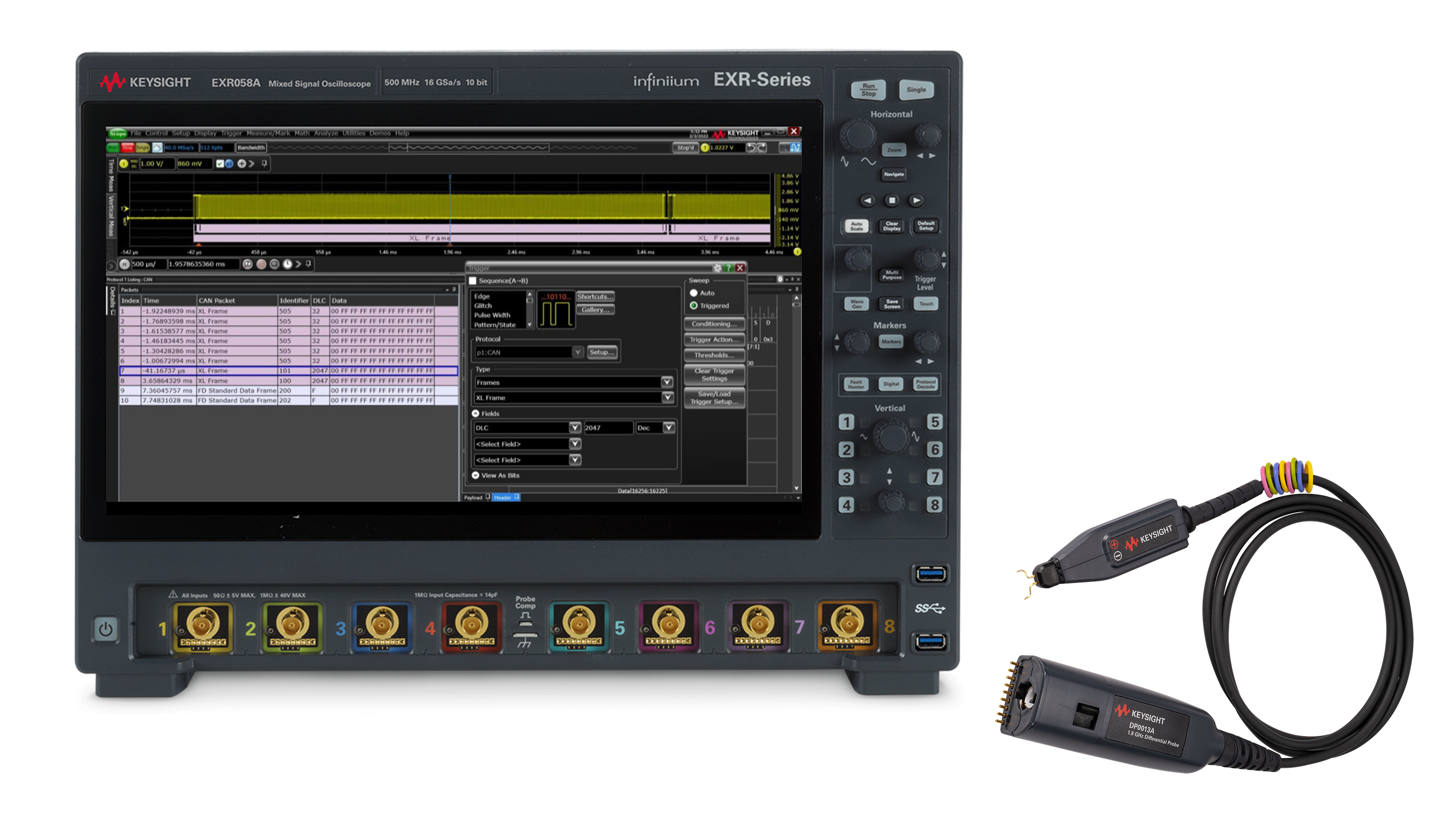
CAN FD and CAN XL Debug Solution
See Demo of CAN FD and CAN XL Debug Solution
Explore Products in Our CAN FD and CAN XL Debug Solution
-

![]()
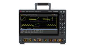
EXR058A Infiniium EXR-Series Oscilloscope: 500 MHz, 8 Channels
-
![]()
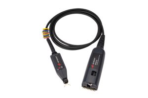
DP0011A Differential Active Probe, 500 MHz
-


![]()
D9010AUTP Automotive Protocol Decode/Trigger Software (CAN, CAN FD, CAN XL, LIN FlexRay, SENT) for Infiniium Oscilloscopes


Discover Resources and Insights
Additional Resources for CAN FD and CAN XL Debugging
Related Use Cases

-
![]()
Learn More
How to Find Intermittent Errors on Automotive Serial Buses
Find intermittent automotive serial bus errors using an Essential benchtop oscilloscope with hardware-based decoding and segmented memory.
Learn More

-
![]()
Learn More
How to Isolate CAN Bus Arbitration
Isolate CAN bus arbitration using an Essential Benchtop Oscilloscope with zone triggering, CAN message qualification, and segmented memory.
Learn More
-
![]()
Learn More
How to Trace Data Across Automotive Serial Bus Gateways
Trace data across automotive serial bus gateways using an Essential benchtop oscilloscope with dual-bus decoding and a time-interleaved protocol lister.
Learn More

Get in Touch With One of Our Experts
Need help finding the right solution for you?