What are you looking for?
How Does Electric Vehicle Supply Equipment (EVSE) Work?
From EVSE standards to compliance testing
Key Takeaways: EVSE Standards and Testing for Scalable EV Charging
- EVSEs must be carefully engineered for safe and reliable power transfer from the grid to electric vehicle (EV) batteries.
- Since no charging standard has managed to become globally dominant, every EVSE must cater to a variety of global and regional standards.
- Ensuring that EVSEs can charge any type of electric vehicle is crucial to maintaining consumer confidence in the EV industry and e-mobility as a whole.
According to the International Energy Agency's global EV report for 2024, 20% of new cars sold worldwide were electric. EV adoption has been growing at an almost exponential rate over the past seven years.
To sustain such growth, issues such as the availability of public charging points, charging speed, and the range anxiety felt by EV owners or fleet managers must be addressed in every market.
Better electric vehicle supply equipment (EVSE) engineering is the key to addressing these issues. In this article, find out what EVSEs are, how they work, what standards apply to them, and how they can be tested effectively.
Table of Contents
What is EVSE?
Electric Vehicle Supply Equipment (EVSE) is the hardware and software that safely delivers power from the grid to an electric vehicle for charging. EVSE refers to the charging infrastructure behind the safe and efficient transfer of electrical energy from the grid to EVs to recharge their onboard high-capacity drive batteries. Electric vehicle charging stations involve advanced engineering and protocols to be compatible with every type of EV and charging interface while safely delivering the lethal currents required by drive batteries.


How Does EVSE Work?
EVSE infrastructure encompasses everything from home EV chargers to heavy-duty public and fleet EV charging stations. Let's look at some of the key components and considerations of EVSE.
Charging Methods
Two types of charging power are prevalent:
- Alternating current (AC): EVSE supplies AC power at the connector. AC is then converted to DC inside the vehicle to charge the batteries.
- Direct current (DC): EVSE supplies DC power directly to an EV's batteries, bypassing its onboard charger.


Complementary to that is the nature of the conduit used for the power transfer:
- Conductive/wired charging: This is the most common charging option, where a charging cable connects the EVSE to the EV.
- Inductive/wireless charging: Instead of a plug-in cable, it uses inductive or resonant technology to deliver energy electromagnetically to the batteries.
- Pantograph charging: Pantographs connect a vehicle to an overhead charging line. It's used for electric heavy-duty vehicles in fleet and urban settings where quick, automated charging without manual plugging is desirable.
Charging Standards
The charging standards are comprehensive frameworks that cover several aspects of charging between an EVSE and an EV. There's no single globally accepted standard. Instead, a variety of global and regional standards exist:
- Combined Charging System (CCS): The CCS standard specifies aspects such as negotiation of charging parameters, authentication, payment, and advanced features like Plug and Charge (PnC). CCS connectors support both AC and DC charging. The CCS type 1 connector is popular in North America and type 2 in Europe and the rest of the world.
- North American Charging Standard (NACS): The NACS utilizes a single, compact connector for both AC and DC charging.
- CHArge de MOve (CHAdeMO): The CHAdeMO standard is popular in Japan and uses two separate ports for AC and DC charging.
- Guobiao Tuijian (GB/T): These standards are prevalent in China. Previously, they used separate ports for AC and DC; however, the new ChaoJi version will utilize a common port.
- Megawatt Charging System (MCS): The MCS standard enables electric heavy-duty vehicles, such as trucks and buses, to be charged quickly using high-power DC.
These standards cover the following aspects:
- Electrical parameters, including charging levels, supported voltages, currents, and power limits for different speeds of charging
- Connectors, including the shape, pinout, and mechanical locking mechanisms of the physical interfaces
- Communication protocols, including the control signals between EVSEs and EVs and between EVSEs and grids
- Safety mechanisms, such as proper grounding and insulation
Charging Levels
| Charging levels | Type | Power | Voltage | Current | Notes |
|---|---|---|---|---|---|
| AC charging | |||||
| Level 1 charging | AC
|
1-2 kW | 120 V | 10-16 A | For electric bikes |
| Level 2 charging | AC | 7-19 kW | 208-240 V
|
32-80 A | For electric cars |
| DC charging | |||||
| Low-power charging | DC
|
0-8 kW | 0-920+ V | 0-20 A | |
| DC charging | DC
|
8-50 kW | 0-920+ V | 20-125 A | |
| Fast charging | DC
|
50-100 kW | 0-920+ V | 125-250 A | Peak current for at least 30 minutes |
| Ultra-fast charging | DC | 100-150 kW | 0-920+ V | 250-500 A | Peak current for at least 20 minutes |
| High-power charging | DC | 150-450 kW | 0-920+ V | 500+ A | Peak current for at least 10 minutes |
| Megawatt charging system (MCS) | |||||
| MCS level 1 | DC | 0-0.4 MW | 1,250 V | 0-350 A | Non-cooled cable |
| MCS level 2 | DC | 0.4-1.8 MW | 1,250 V | 0-1,500 A | Liquid-cooled cable |
| MCS level 3 | DC | 1.8-3.75 MW | 1,250 V | 0-3,000 A | Liquid-cooled cable and inlet |
| Ruggedized MCS (R-MCS) | DC | 3.75-6 MW | 1,500 V | 0-4,000 A | For harsh environments: mining, aviation, and maritime |
| X-MCS | DC | 12-24 MW | 3,000 V | 0-4,000 A | Upcoming standard |
Charging speed is determined by the charging levels as explained below.
AC charging
The AC charging levels from the Society of Automotive Engineers (SAE) J1772 standard are integrated into CCS:
- Level 1 charging: It relies on a standard 120 volts (V) AC household outlet that can deliver around 1-2 kilowatts (kW) of power at 10-16 amps (A). It's suitable for small electric bikes, not electric cars.
- Level 2 charging: Most home chargers and public EV charging solutions use level 2 chargers. They operate at 208-240 V AC. Power ranges from 7-19 kW and current from 32-80 A.
DC charging
CCS specifies these five DC power classes:
- Low-power charging: Charge power remains below 8 kW.
- DC charging: These EVSE can deliver above 8 kW up to 50 kW.
- Fast charging (FC): FC EVSE can supply 50-100 kW for at least 30 minutes.
- Ultra-fast charging (UFC): They can deliver 100-150 kW for at least 20 minutes.
- High-power charging (HPC): HPC EVSE can supply more than 150 kW for at least 10 minutes.
These classes and power levels are also used for bidirectional charging.
Megawatt charging system (MCS)
Megawatt charging is intended for heavy-duty electric buses, semis, earth-moving machinery, aviation equipment, and even maritime vessels. It involves DC voltages of 1,000+ V and currents from several hundreds to 4,000 A. Existing MCS systems can supply 0.4-6 megawatts (MW), and future systems are being designed for 12-24 MW.
MCS currently specifies five power levels:
- MCS level 1: Level 1 EVSE uses non-cooled charging cables to deliver up to 350 A at 1,250 V.
- MCS level 2: They can supply up to 1,500 A at 1,250 V using liquid-cooled charging cables.
- MCS level 3: Level 3 EVSE uses liquid cooling for both charging cables and EV inlets to supply up to 3,000 A at 1,250 V.
- Ruggedized MCS (R-MCS): Ruggedized MCS can deliver up to six MW with currents reaching 4,000 A at 1,500 V. It's designed for harsh environments like mining, aviation, and maritime.
- X-MCS: This upcoming standard will enhance R-MCS to deliver 12-24 MW.

 levels")
Communication Between EVSE and EV
The EVSE and EV communicate with each other using protocols like the International Organization for Standardization (ISO) 15118 specifications that define how to:
- negotiate charging levels
- control the charging sequence involving handshakes and authentication
- facilitate smart charging (where charging times and rates are based on real-time grid load, energy prices, and renewable energy availability)
- implement PnC with automated authentication and billing
- ensure safety through state-of-charge reporting and error handling
- communicate securely
Communication Between EVSE and Management Systems
EVSE and central management systems communicate for remote management, smart charging, billing, metering, and network operations. Different back-end protocol alternatives exist, like:
Connectors
Each charging standard includes specifications for the connector shapes, pinouts, and locking mechanisms.


Safety Mechanisms
Charging standards specify safety mechanisms like:
- grounding and insulation to prevent electric shocks
- ensuring that power is delivered only when a secure connection is established
- mechanisms to detect overcurrent, overvoltage, short circuits, ground faults, and abnormal temperatures, and to shut down power safely
- temperature monitoring, especially for high-power DC charging
Grid Integration
EVSEs are increasingly integrated into smart grids to implement:
- V2G (vehicle-to-grid) for bidirectional energy flow
- load balancing
- demand response
- smart charging based on grid load and renewable energy availability
Some EVSEs can be powered by solar energy and other distributed energy resources.
What Is Bidirectional Charging?
Bidirectional charging means EVs not only consume power for charging but also supply back excess stored energy to the grid or a building for reduced net energy usage.
What Do V1G, V2G, and V2H Mean?
- V1G (vehicle-one-grid) is the conventional, one-way power flow from the grid to an EV.
- V2G (vehicle-to-grid) refers to EVs discharging their stored energy back to the grid when needed to help with stability, frequency regulation, and load balancing.
- V2H (vehicle-to-home) is similar to V2G, but the stored energy goes back to a home or building instead of the grid.
- The ISO 15118 standard facilitates seamless bidirectional power transfer (BPT) through features like PnC, negotiation of power flow, automatic authentication, and billing.
- The OCPP standard addresses key data, control, and network aspects relevant to V2G/V2H operations, like authorization and metering.

Why Is EVSE Testing Important for Ensuring Safe and Reliable EV Charging?
For safe and reliable EV charging, thorough EVSE testing is essential. EVSE testing must address the aspects outlined below:
- Interoperability: EVSE must be able to charge every EV of any manufacturer or model successfully to maintain consumer confidence in e-mobility.
- Protocol conformance: Many inoperability issues stem from communication errors. With numerous EVSE standards and advanced features, thorough protocol conformance testing is crucial for ensuring interoperability.
- Safety: EVSE testing validates safety-critical events, such as emergency shutdowns and the discharge of internal high-voltage sources. Insulation resistance testing is also a key safety check.
- Performance: EVSE testing must validate performance under fault conditions, extreme temperatures, and dynamic grid events.
- Simulation: Realistic simulations of different EVs, batteries, positive scenarios, and error conditions enable pushing systems to their limits from the early stages at low cost without risking EVSE installations or EVs.
- Automation: Test automation enables repeatable evaluation through hundreds of tests, continuously verifying interoperability and conformance.
- Electromagnetic compatibility (EMC): EVSE emissions can interfere with other electronic devices and wireless communications. EMC testing ensures that EVSEs always operate in their intended electromagnetic environment.
- Protocol security: Secure authentication and data exchange are verified by testing transport layer security, public key infrastructure for PnC, and XML security for application layer integrity and non-repudiation.
- Debugging: For debugging and root cause analysis, protocol trace viewers and man-in-the-middle analyzers enable observation, capture, and decoding of communication and power signals between an EV and EVSE.
What Global Standards and Certifications Apply to EVSE Testing?
Various standards and certifications apply to EVSEs and EVSE testing. They're managed by organizations like:
- ISO
- International Electrotechnical Commission (IEC)
- Institute of Electrical and Electronics Engineers (IEEE)
- Federal Communications Commission (FCC)
- German Institute for Standardization (DIN)
- Underwriters Laboratories (UL)
The sections below describe important:
- charging standards
- communication protocols
- connector standards
- electrical safety standards
- EMC standards
- grid integration protocols
- EVSE certifications
Core Charging Standards
| Charging standard | Description | Government body | Region of application |
|---|---|---|---|
| Combined Charging System (CCS) |
|
CharIN |
|
| North American Charging Standard (NACS) / SAE J3400 |
|
Tesla / SAE |
|
| CHArge de MOve (CHAdeMO) |
|
CHAdeMO Association |
|
| Guobiao Tuijian (GB/T) |
|
Standardization Administration of China (SAC) |
|
| ChaoJi |
|
CHAdeMO Association + China Electricity Council (CEC) |
|
| Megawatt Charging System (MCS) |
|
CharIN |
|
EVSE-To-EV Communication Protocols
| Standard/Specification | Description | Government body | Region of application |
|---|---|---|---|
| ISO 15118 Series |
|
ISO |
|
| ISO 15118-2 |
|
||
| ISO 15118-3 |
|
||
| ISO 15118-4 ISO 15118-5 |
|
||
| ISO 15118-8 |
|
||
| ISO 15118-20 |
|
||
| DIN SPEC 70121 |
|
DIN |
|
| IEC 61850 |
|
IEC |
|
| IEEE 2030.5 |
|
IEEE |
|
| GB/T 27930 |
|
SAC |
|
Connector Standards
| Standard/Specification | Description | Government body | Region of application |
|---|---|---|---|
| SAE J1772 (Type 1) |
|
SAE |
|
| IEC 62196-2 (Type 2) |
|
IEC |
|
| IEC 62196-3 |
|
IEC |
|
| GB/T 20234.2 |
|
SAC |
|
| GB/T 20234.3 |
|
SAC |
|
Electrical Safety Standards
| Standard/Specification | Description | Government body | Region of application |
|---|---|---|---|
| IEC 61851 Series |
|
IEC |
|
| IEC 61851-1 |
|
|
|
| IEC 61851-23 |
|
|
|
| UL 2594 |
|
UL |
|
| UL 2231 |
|
UL |
|
| UL 508A |
|
UL |
|
| SAE J2953/1 & J2953/2 |
|
SAE |
|
| ISO 6469 |
|
ISO |
|
| ISO/SAE 21434 |
|
ISO / SAE |
|
EMC Standards
| Standard/Specification | Description | Government body | Region of application |
|---|---|---|---|
| IEC 61000 Series |
|
IEC |
|
| EN 61000-6-1 EN 61000-6-3 |
|
CENELEC |
|
| IEC 61851-21 |
|
IEC |
|
| CISPR 11 / EN 55011 |
|
CISPR (part of IEC) |
|
| FCC Part 15 Class A FCC Part 15 Class B |
|
FCC |
|
| ICES-003 |
|
ISED Canada |
|
Grid Integration Protocols
| Standard/Specification | Description | Government body | Region of application |
|---|---|---|---|
| Open Charge Point Protocol (OCPP) |
|
Open Charge Alliance (OCA) |
|
| Open Charge Point Interface (OCPI) |
|
EVRoaming Foundation |
|
| UL 1741 SA / SB |
|
UL |
|
| EN 50549 |
|
CENELEC |
|
| IEEE 1547 |
|
IEEE |
|
| Open Automated Demand Response (OpenADR) |
|
OpenADR Alliance |
|
EVSE Certifications
| Certification / Body | Description |
|---|---|
| CharIN Certification |
|
| Open Charge Alliance (OCA) |
|
| UL Mark |
|
| CE Mark |
|
How Do Interoperability Tests Ensure That EVSE Works With Different EV Models?
Interoperability testing uses specialized test systems and methods to ensure seamless communication and power transfer between different grids, EVSE, and EVs. Let's look at these techniques below.
- Conformance testing: Rigorous protocol conformance verification using official test case specifications of various charging standards ensures strict adherence to the rules that govern charging negotiations. Testing negotiation and fallback behaviors ensures compatibility with both new and legacy EV models. EVSEs can be designed to support evolving standards.
- EVSE emulation: The test system emulates a configurable AC or DC EVSE to test any EV.
- EV emulation: The test system acts as a universal configurable EV that enables functional, safety, and performance testing of EVSE. It uses an electronic load and a regenerative power supply to simulate EV behavior.
- Battery emulation: The test system can emulate any EV battery capacity, technology, state of charge, or internal resistance.
- Man-in-the-middle testing: A test system is placed between a real EV and a real EVSE to passively monitor, capture, and decode the communication and power signals. This enables real-time analysis of errors and their causes during an actual charging session.
- Automated testing: Extensive libraries of automated test cases based on industry specifications can be run systematically and continuously validate behaviors, inject modified parameters, and set pass/fail conditions.
- Component-level testing: The EV communication controller (EVCC) in the vehicle and the supply equipment communication controller (SECC) in the charger are tested individually using a communication interface tester that emulates the counterpart controller and executes pre-programmed test cases.
What’s the Difference Between EVSE Conformance Testing and Functional Testing?
EVSE conformance testing rigorously checks adherence to official charging standards and communication protocols, including its behaviors under normal, extreme, and error conditions. It's a prerequisite for type approval and certification.
Functional testing goes beyond conformance testing, verifying that an EVSE is behaving and performing as intended and expected by users.
How Do Engineers Simulate Real-World Charging Conditions in the Lab?
For simulating diverse real-world conditions, engineers use the following techniques:
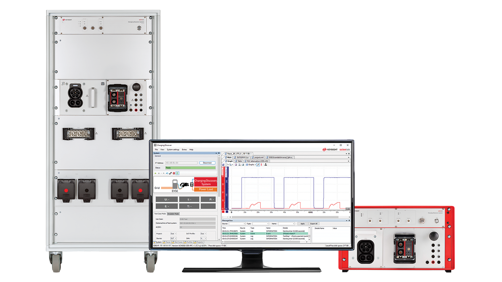
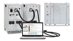
- EV and EVSE emulation: Keysight's Megawatt Charging Discovery System (CDS) can emulate any EVSE or EV, including electrical interfaces, communication signals, and energy transfer according to selected charging standards. It can emulate power from 10 kW to 2,250 kW and currents up to 1,500 A.
- Communication monitoring: Devices like the SL1550A EV – EVSE Charging Communication Interface Tester can emulate charging controllers for hardware-in-the-loop integration tests. Protocol trace viewers and tracers are used to observe, capture, and decode communication messages on the charging line.
- Power flow emulation: AC and DC emulators and bidirectional power sources provide the necessary power flow.
- Faults: Fault conditions (like invalid charging profiles, expired certificates, and communication errors) are intentionally injected using man-in-the-middle systems to assess reliability, vulnerabilities, and limits.
- EMC environments: EMC measurements are made inside anechoic test chambers during AC and DC charging.


How Can EVSE Testing Help Prevent Failures in High-Power Fast Chargers?


Due to the increased dangers of high-power fast charging, EVSE testing must be more meticulous in these areas:
- Safety mechanisms: Overvoltage, overcurrent, and over-temperature protection must be tested thoroughly. Emergency stop functions, output inhibit modes, and proper insulation monitoring are critical.
- Thermal management: High-power charging generates significant heat. Testing involves using liquid-cooled charging adapters and cooling units to verify the effectiveness of the thermal management system, thereby preventing overheating failures. Power quality and thermal behavior analysis are crucial for maintaining the correct functioning of MCS.
- Fault conditions: Emulation enables the safe reproduction of hazardous problems, such as power line breaks during charging and insulation faults, which are difficult and dangerous to conduct in real life.
What Role Does Battery Emulation Play in EVSE Testing and Validation?
Battery emulation enables comprehensive, safe, and efficient verification of EVSEs without using physical EVs.
Simulators, often regenerative DC emulators or electronic loads, reproduce realistic behaviors of a wide range of EV batteries.
Unlike real EV batteries, which have limited capacities and require recharging, emulators enable continuous testing for extended durations.
Emulators accurately simulate various battery conditions, including:
- changes in internal resistance over state of charge
- specific thresholds
- boundary values
- overvoltage and overcurrent events
- fault conditions like power line breaks during charging
How Do Keysight Charging Test Solutions Facilitate the EVSE Certification Process?
EVSE certification is accelerated by using Keysight's charging test solutions outlined below:
- Charging Discovery System (CDS): CDS is a family of modular, all-in-one solutions to emulate electrical interfaces and communication signals, capable of testing AC and DC charging interfaces up to 2,250 kW. As a CharIN validated conformance test system, it's specifically approved for CharIN CCS conformance testing and individual product development testing of EVSEs.
- Communication interface testers: Devices like the SL1550A enable component-level testing of EVCCs and SECCs and communication protocols (like CCS and NACS).
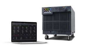
- Power emulators: Regenerative power supplies for AC (like the SL1200A Series) and DC (like the SL1800A Series and RP7900 Series) can source and sink power to simulate grids and batteries.
- Test robotics: The SL1562A Charging Human Machine Interface Actuator and the SL1563A EVSE Card Swiper Test Robot enable testing of physical interactions like button presses and card swiping.
These hardware systems are enabled by the following test and simulation software:
- Control tools: The SL2000A Charging Discover Software controls the CDS, records test sequences, visualizes measurements, and generates test reports.
- Test case libraries: The SL1300A Test Case Library and SL14XXA Scienlab Test Case Library provide extensive pre-programmed test cases for automated conformance and interoperability testing.
- Smart charging emulation: The SL1470A Smart Charging Emulation Software enables flexible EV/EVSE emulation for CCS, V2G, and PnC testing.
- Communication testing: The SL1471A Charging Communication Test Automation Software enables automated conformance and interoperability testing.
- Analysis tools: The SL1487A Charging Protocol Trace Viewer decodes and analyzes captured communication packets.


Discover Related Use Cases


Want help or have questions?