Learn More
keysight:dtx/solutions/facets/development-area/high-speed-digital,keysight:dtx/solutions/facets/design-and-test-product/oscilloscope---logic-analyzer,segmentation:business-unit/CSG,keysight:product-lines/1a,keysight:dtx/solutions/facets/industry/automotive,segmentation:funnel/mofu,segmentation:campaign/Digital_General_Purpose,segmentation:product-category/Oscilloscopes_BERTs_AWGs,segmentation:product-category/Oscilloscopes_BERTs_AWGs/Oscilloscopes_upto_2GHz,segmentation:search-relevance-product/hardware,segmentation:search-relevance-product/software,keysight:dtx/solutions/facets/workflow-stage/functional-test,keysight:models/hd/hd304mso,keysight:models/hd/hd300autakeysight:dtx/solutions/facets/development-area/high-speed-digital,keysight:dtx/solutions/facets/design-and-test-product/oscilloscope---logic-analyzer,segmentation:business-unit/CSG,keysight:product-lines/1a,keysight:dtx/solutions/facets/industry/automotive,segmentation:funnel/mofu,segmentation:campaign/Digital_General_Purpose,segmentation:product-category/Oscilloscopes_BERTs_AWGs,segmentation:product-category/Oscilloscopes_BERTs_AWGs/Oscilloscopes_upto_2GHz,segmentation:search-relevance-product/hardware,segmentation:search-relevance-product/software,keysight:dtx/solutions/facets/workflow-stage/functional-test,keysight:models/hd/hd304mso,keysight:models/hd/hd300autakeysight:dtx/solutions/facets/development-area/high-speed-digital,keysight:dtx/solutions/facets/design-and-test-product/oscilloscope---logic-analyzer,segmentation:business-unit/CSG,keysight:product-lines/1a,keysight:dtx/solutions/facets/industry/automotive,segmentation:funnel/mofu,segmentation:campaign/Digital_General_Purpose,segmentation:product-category/Oscilloscopes_BERTs_AWGs,segmentation:product-category/Oscilloscopes_BERTs_AWGs/Oscilloscopes_upto_2GHz,segmentation:search-relevance-product/hardware,segmentation:search-relevance-product/software,keysight:dtx/solutions/facets/workflow-stage/functional-test,keysight:models/hd/hd304mso,keysight:models/hd/hd300autakeysight:dtx/solutions/facets/development-area/high-speed-digital,keysight:dtx/solutions/facets/design-and-test-product/oscilloscope---logic-analyzer,segmentation:business-unit/CSG,keysight:product-lines/1a,keysight:dtx/solutions/facets/industry/automotive,segmentation:funnel/mofu,segmentation:campaign/Digital_General_Purpose,segmentation:product-category/Oscilloscopes_BERTs_AWGs,segmentation:product-category/Oscilloscopes_BERTs_AWGs/Oscilloscopes_upto_2GHz,segmentation:search-relevance-product/hardware,segmentation:search-relevance-product/software,keysight:dtx/solutions/facets/workflow-stage/functional-test,keysight:models/hd/hd304mso,keysight:models/hd/hd300autakeysight:dtx/solutions/facets/development-area/high-speed-digital,keysight:dtx/solutions/facets/design-and-test-product/oscilloscope---logic-analyzer,segmentation:business-unit/CSG,keysight:product-lines/1a,keysight:dtx/solutions/facets/industry/automotive,segmentation:funnel/mofu,segmentation:campaign/Digital_General_Purpose,segmentation:product-category/Oscilloscopes_BERTs_AWGs,segmentation:product-category/Oscilloscopes_BERTs_AWGs/Oscilloscopes_upto_2GHz,segmentation:search-relevance-product/hardware,segmentation:search-relevance-product/software,keysight:dtx/solutions/facets/workflow-stage/functional-test,keysight:models/hd/hd304mso,keysight:models/hd/hd300autakeysight:dtx/solutions/facets/development-area/high-speed-digital,keysight:dtx/solutions/facets/design-and-test-product/oscilloscope---logic-analyzer,segmentation:business-unit/CSG,keysight:product-lines/1a,keysight:dtx/solutions/facets/industry/automotive,segmentation:funnel/mofu,segmentation:campaign/Digital_General_Purpose,segmentation:product-category/Oscilloscopes_BERTs_AWGs,segmentation:product-category/Oscilloscopes_BERTs_AWGs/Oscilloscopes_upto_2GHz,segmentation:search-relevance-product/hardware,segmentation:search-relevance-product/software,keysight:dtx/solutions/facets/workflow-stage/functional-test,keysight:models/hd/hd304mso,keysight:models/hd/hd300autakeysight:dtx/solutions/facets/development-area/high-speed-digital,keysight:dtx/solutions/facets/design-and-test-product/oscilloscope---logic-analyzer,segmentation:business-unit/CSG,keysight:product-lines/1a,keysight:dtx/solutions/facets/industry/automotive,segmentation:funnel/mofu,segmentation:campaign/Digital_General_Purpose,segmentation:product-category/Oscilloscopes_BERTs_AWGs,segmentation:product-category/Oscilloscopes_BERTs_AWGs/Oscilloscopes_upto_2GHz,segmentation:search-relevance-product/hardware,segmentation:search-relevance-product/software,keysight:dtx/solutions/facets/workflow-stage/functional-test,keysight:models/hd/hd304mso,keysight:models/hd/hd300autakeysight:dtx/solutions/facets/development-area/high-speed-digital,keysight:dtx/solutions/facets/design-and-test-product/oscilloscope---logic-analyzer,segmentation:business-unit/CSG,keysight:product-lines/1a,keysight:dtx/solutions/facets/industry/automotive,segmentation:funnel/mofu,segmentation:campaign/Digital_General_Purpose,segmentation:product-category/Oscilloscopes_BERTs_AWGs,segmentation:product-category/Oscilloscopes_BERTs_AWGs/Oscilloscopes_upto_2GHz,segmentation:search-relevance-product/hardware,segmentation:search-relevance-product/software,keysight:dtx/solutions/facets/workflow-stage/functional-test,keysight:models/hd/hd304mso,keysight:models/hd/hd300autakeysight:dtx/solutions/facets/development-area/high-speed-digital,keysight:dtx/solutions/facets/design-and-test-product/oscilloscope---logic-analyzer,segmentation:business-unit/CSG,keysight:product-lines/1a,keysight:dtx/solutions/facets/industry/automotive,segmentation:funnel/mofu,segmentation:campaign/Digital_General_Purpose,segmentation:product-category/Oscilloscopes_BERTs_AWGs,segmentation:product-category/Oscilloscopes_BERTs_AWGs/Oscilloscopes_upto_2GHz,segmentation:search-relevance-product/hardware,segmentation:search-relevance-product/software,keysight:dtx/solutions/facets/workflow-stage/functional-test,keysight:models/hd/hd304mso,keysight:models/hd/hd300autakeysight:dtx/solutions/facets/development-area/high-speed-digital,keysight:dtx/solutions/facets/design-and-test-product/oscilloscope---logic-analyzer,segmentation:business-unit/CSG,keysight:product-lines/1a,keysight:dtx/solutions/facets/industry/automotive,segmentation:funnel/mofu,segmentation:campaign/Digital_General_Purpose,segmentation:product-category/Oscilloscopes_BERTs_AWGs,segmentation:product-category/Oscilloscopes_BERTs_AWGs/Oscilloscopes_upto_2GHz,segmentation:search-relevance-product/hardware,segmentation:search-relevance-product/software,keysight:dtx/solutions/facets/workflow-stage/functional-test,keysight:models/hd/hd304mso,keysight:models/hd/hd300autakeysight:dtx/solutions/facets/development-area/high-speed-digital,keysight:dtx/solutions/facets/design-and-test-product/oscilloscope---logic-analyzer,segmentation:business-unit/CSG,keysight:product-lines/1a,keysight:dtx/solutions/facets/industry/automotive,segmentation:funnel/mofu,segmentation:campaign/Digital_General_Purpose,segmentation:product-category/Oscilloscopes_BERTs_AWGs,segmentation:product-category/Oscilloscopes_BERTs_AWGs/Oscilloscopes_upto_2GHz,segmentation:search-relevance-product/hardware,segmentation:search-relevance-product/software,keysight:dtx/solutions/facets/workflow-stage/functional-test,keysight:models/hd/hd304mso,keysight:models/hd/hd300autakeysight:dtx/solutions/facets/development-area/high-speed-digital,keysight:dtx/solutions/facets/design-and-test-product/oscilloscope---logic-analyzer,segmentation:business-unit/CSG,keysight:product-lines/1a,keysight:dtx/solutions/facets/industry/automotive,segmentation:funnel/mofu,segmentation:campaign/Digital_General_Purpose,segmentation:product-category/Oscilloscopes_BERTs_AWGs,segmentation:product-category/Oscilloscopes_BERTs_AWGs/Oscilloscopes_upto_2GHz,segmentation:search-relevance-product/hardware,segmentation:search-relevance-product/software,keysight:dtx/solutions/facets/workflow-stage/functional-test,keysight:models/hd/hd304mso,keysight:models/hd/hd300autakeysight:dtx/solutions/facets/development-area/high-speed-digital,keysight:dtx/solutions/facets/design-and-test-product/oscilloscope---logic-analyzer,segmentation:business-unit/CSG,keysight:product-lines/1a,keysight:dtx/solutions/facets/industry/automotive,segmentation:funnel/mofu,segmentation:campaign/Digital_General_Purpose,segmentation:product-category/Oscilloscopes_BERTs_AWGs,segmentation:product-category/Oscilloscopes_BERTs_AWGs/Oscilloscopes_upto_2GHz,segmentation:search-relevance-product/hardware,segmentation:search-relevance-product/software,keysight:dtx/solutions/facets/workflow-stage/functional-test,keysight:models/hd/hd304mso,keysight:models/hd/hd300autakeysight:dtx/solutions/facets/development-area/high-speed-digital,keysight:dtx/solutions/facets/design-and-test-product/oscilloscope---logic-analyzer,segmentation:business-unit/CSG,keysight:product-lines/1a,keysight:dtx/solutions/facets/industry/automotive,segmentation:funnel/mofu,segmentation:campaign/Digital_General_Purpose,segmentation:product-category/Oscilloscopes_BERTs_AWGs,segmentation:product-category/Oscilloscopes_BERTs_AWGs/Oscilloscopes_upto_2GHz,segmentation:search-relevance-product/hardware,segmentation:search-relevance-product/software,keysight:dtx/solutions/facets/workflow-stage/functional-test,keysight:models/hd/hd304mso,keysight:models/hd/hd300auta
How to Characterize Automotive Serial Buses
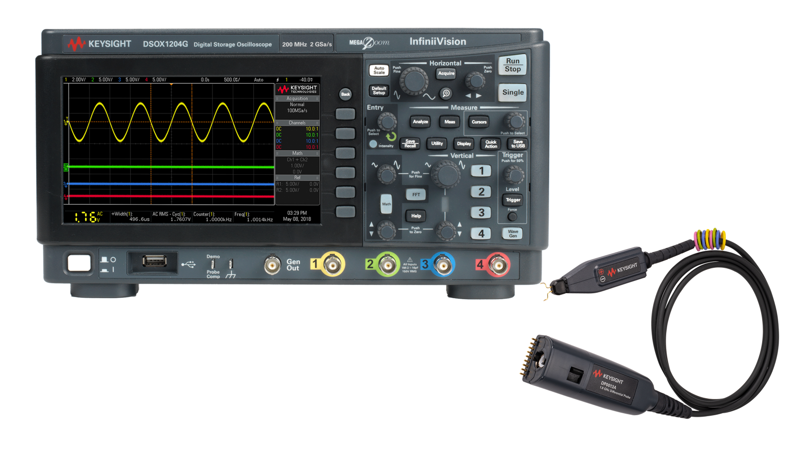
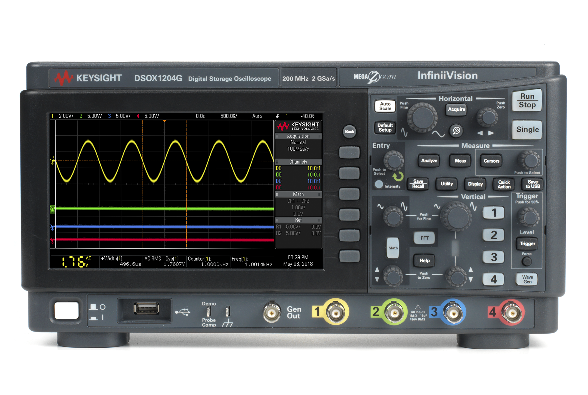
Characterizing automotive serial buses requires debugging and correlating data transfers with other mixed-signal interactions. Learn how to use an oscilloscope and protocol decode software to debug CAN, CAN FD, CAN XL, LIN, and other automotive serial bus standards.
Learn More