Toggle Menu
Confirm Your Country or Area
Please Confirm
Confirm your country to access relevant pricing, special offers, events, and contact information.
Confirm Your Country or Area
Please Confirm
Confirm your country to access relevant pricing, special offers, events, and contact information.

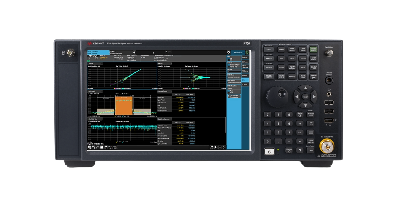
Testing the performance of a power amplifier (PA) requires a vector signal generator and a signal analyzer running power amplifier measurement software fed back into the input of the signal generator. The signal generator provides a digitally pre-distorted signal as input to the power amplifier to compensate for its non-linear behavior.
A signal analyzer is used to measure the signal quality generated by the PA and apply any necessary post-DPD processing or measurements. The signal analyzer measures the quality of the signal in terms of error vector magnitude (EVM), phase error, and other performance parameters like adjacent channel leakage ratio (ACLR).
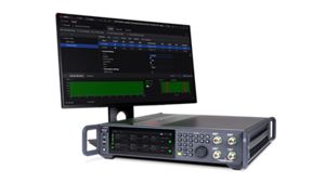
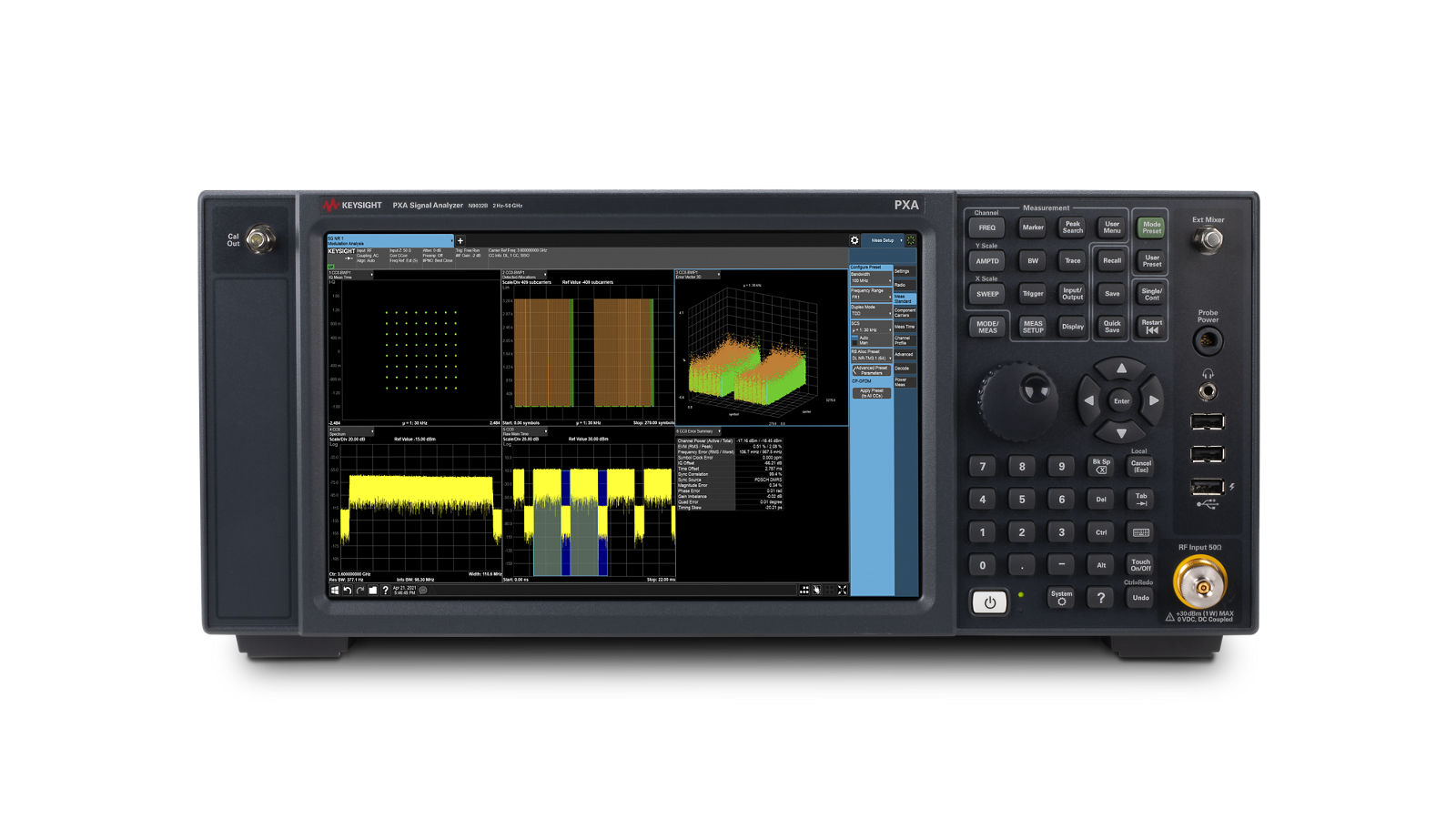
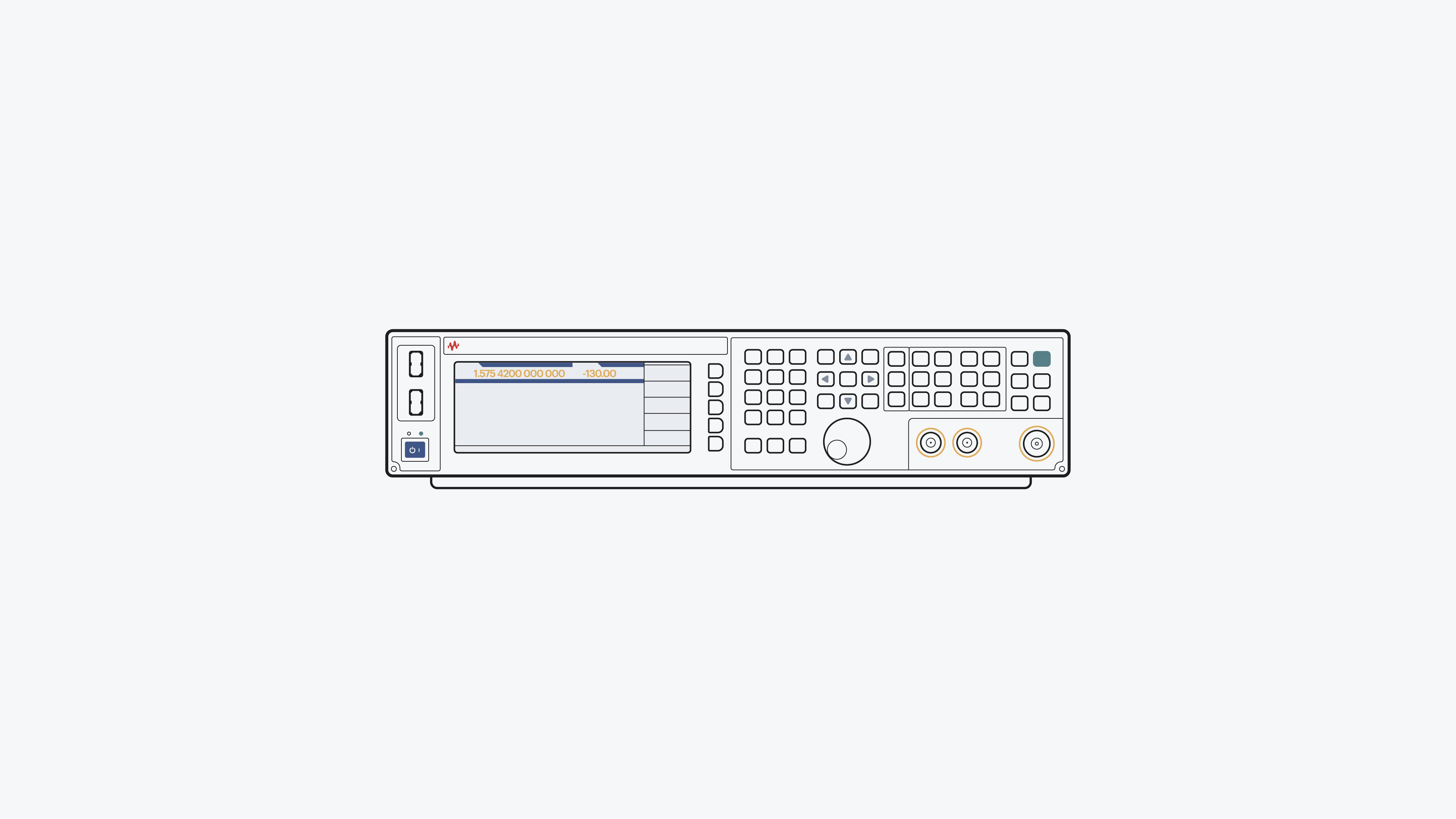
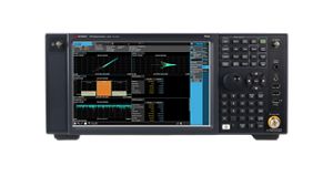
Power amplifier test requires a signal generator and a signal analyzer running DPD software. The Keysight power amplifier test solution requires the Keysight MXG signal generator, with its low error vector magnitude (EVM) and adjacent channel leakage ratio (ACLR), and the PXA signal analyzer running Keysight Power Amplifier Measurement Application software. The software generates a pre-DPD waveform transmitted by the signal generator, and analyzes the captured waveform from the signal analyzer, validating the amplified waveform versus the post-DPD target. Pre- and post-DPD measurement results are displayed on one screen for ease of comparison. The PXA signal analyzer provides key measurements like EVM and ACLR to determine the signal quality from the power amplifier.
Additional resources for RF power amplifier test
Testing digital wideband transceivers requires a hybrid solution combining a signal generator and a network analyzer. Learn how to perform digital RF stimulus response tests while achieving digital-integrated RF front-end characterization.
Learn more
![]()
Characterizing 802.11ad devices requires the generation and analysis of waveforms at baseband, IF, RF, and mmWave frequencies. Learn how to characterize wireless gigabit devices with three essential elements — waveform generation, frequency conversion, signal, modulation, and spectrum analysis.
Learn more
![]()
Engineers researching 6G H-band implementations require a wideband modulated signal generator with a high carrier frequency signal to evaluate 6G RF waveform performance. Learn how to characterize sub-THz wideband signals in the H-band using a 6G research testbed with custom modulation signal generation software.
Learn more
![]()

Need help finding the right solution for you?