What are you looking for?
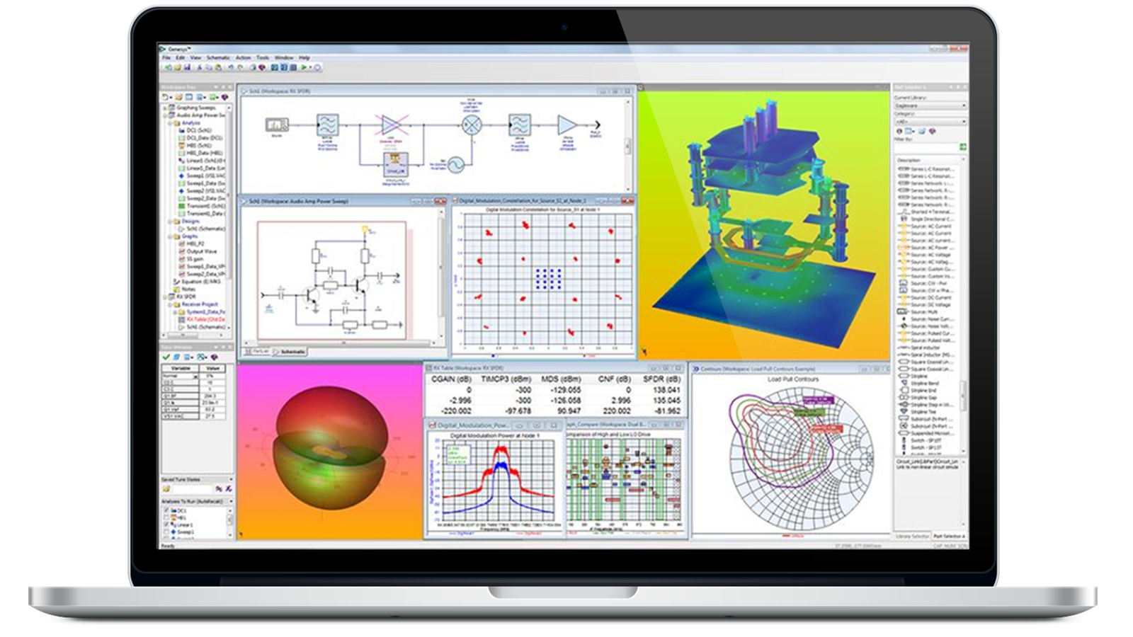
RF and Microwave Circuit Design Software
Achieve consistent RF design wins
As radio-frequency (RF) applications move into millimeter-wave (mmWave) frequencies, integration is becoming denser. This density increases the complexity of correctly assembling, simulating, and verifying multi-technology RF modules. Keysight's RF Design Suite helps reduce costly hardware failures by enabling intelligent integration of modules that interconnect circuit design softwares, including radio-frequency integrated circuits (RFIC), monolithic microwave integrated circuits (MMIC), laminate, wafer-level packaging, antennas, and printed circuit boards (PCBs) into dense 3D structures.
See what's new
First by Design – Why Keysight Labs Uses Keysight RF EDA Software
Keysight’s mmWave systems design group values the ability to perform simulation design from the beginning, inception block diagram architecture phase, through to the end product.
This approach includes full electromagnetic electrothermal accounting and simulation of manufacturing tolerances, which yields manufacturability and product delivery.
“This comprehensive design approach really allows us to predict reality”.
AI-Ready RF Circuit Design
As we strive for greater engineering productivity, faster time to market, and optimized decision-making from a sea of data, Artificial Intelligence (AI) and Machine Learning (ML) provide exciting new tools to accelerate the engineering lifecycle. Keysight can help you start automating your workflows and add in your proprietary optimization algorithms.
Learn more
Learning Hub: AI-Assisted Design for 5G/6G Workflows
White Paper: Accelerate your Digital Transformation with ADS Python Automation
Video: Use AI to create a simulation model
View Webinar: Automation and AI in 3D Multiphysics Microwave Designs
Designing for 3D Heterogeneous Integration (3DHI)
3D Heterogeneous Integration requires a workflow comprising several software tools in the flow, including Keysight ADS, Cadence Virtuoso, and Synopsys Customer Compiler. Accounting for performance design improvement revisions requires a laborious translation between platforms. Dense design integration into one 3D physical structure requires a shared database that spans technology boundaries and hierarchies so that revisions can be traced across the design.
Learn more
Demo Video: Accelerating 3DHI Module Design with Keysight EDA
Webinar: Designing 3DHI Modules in Phased Array Systems
Solution Brief: RF 3DHI Modules and RF Chiplet Designs Crucial to 6G RF Systems
Next Generation Multi-domain Circuit Simulation & Optimization
As we strive for greater engineering productivity, faster time to market, and optimized decision-making from a sea of data, Artificial Intelligence (AI) and Machine Learning (ML) provide exciting new tools to accelerate the engineering lifecycle. Keysight can help you start automating your workflows and add in your proprietary optimization algorithms.
Learn more
Blog: What is the Next Generation in RF Circuit Simulation & Optimization?
Brochure: RF Circuit Simulation Professional
Technical Paper: Bring Your Own Code: A Simulation Framework to Harness Optimization
View Webinar: Next Generation AI-Ready RF Circuit Simulation and Optimization
White Paper: The Next-Generation of Circuit Simulation in RF EDA
Circuit-System Co-Simulation: RF System Explorer
Learn how your circuit design impacts overall system performance with RF System Explorer (RFSE) in ADS. Use Extracted Behavioral Models (EBMs) of your actual ADS designs directly in RF lineup analyses and streamline your design process.
Learn more
Circuit-System Co-Simulation: DPD Explorer
Discover how DPD Explorer in ADS helps PA designers tackle efficiency and linearization challenges. See how Power Added Efficiency measurement and Envelope Tracking can boost your amplifier’s performance for wideband applications.
Learn more
Circuit-System Co-Simulation: Modulation Explorer
Modulation Explorer enables users to configure various signal formats such as 5G NR, LTE, WLAN, and I/Q user definitions to test their circuit design in ADS. The signal is generated and fed into the circuit design, and measurements are performed on the circuit's output, like Spectrum, ACLR, EVM, etc.
Learn more
Vendor Component Libraries
Keysight EDA actively engages with component manufacturers to create model libraries that will enable you to access the latest models and technologies. There are numerous vendors providing libraries for Keysight's Advanced Design System (ADS) RF and Microwave Design Software.
Learn More


Design RFIC and MMIC with Foundry Process Design Kits (PDK)
ADS is endorsed by leading Silicon and III-V foundries to enable the design of high performance RFICs and MMICs that must work when integrated in multi-technology RF modules which combine fan-out wafer level packaging (FOWLP), 3D interconnects, laminates and antennas.
Now RFICs and MMICs need not be designed in isolation, but proven within the final application such as 5G, automotive radars, or wireless networking, so that you can consistently achieve design wins with your customers.
Learn More

 Foundry Logos")
More Circuit Design Software

Find the Model that's Right for You

Software Enterprise Agreement
Deploy a Keysight Software Enterprise Agreement to capture continuous value for your organization. Enterprise Agreements deliver flexible, cost-effective access to Keysight’s broad software portfolio through a re-mixable license pool.
Protect Your Innovation Investment


Innovate at speed by ensuring up-to-date application software & firmware and expert technical support at our fastest available times.


Software licensing, terms, and types
Keysight software licensing options provide flexibility and support. Choose your terms, choose your type, and keep control of your budget.


Manage your Keysight software, view and request licenses, and get the latest software updates.
Featured Resources


Frequently Asked Questions
RF circuit design involves designing and simulating electronic circuits that operate in radio frequencies (RF) and millimeter-wave frequencies, typically ranging from a few kHz to several hundred GHz. Various applications use these circuits such as wireless communication, radar systems, satellite communication, automotive, and more.
Circuit simulation is a computational technique used to model and analyze the behavior of electronic circuits. The first step is creating a mathematical circuit model representing the circuit's components and interconnections. Mathematical equations or models describe each component capturing its behavior under different operating conditions. After modeling the circuit, engineers use simulation software to solve the equations and analyze the circuit's behavior. Today’s increasingly complex, dense RF circuit designs require complex simulators capable of handling large and intricate circuits.
The critical components of an RF circuit include amplifiers, oscillators, filters, mixers, modulators / demodulators, antennas, transmission lines, and matching networks.
The Smith chart represents complex impedance and reflection coefficient values in a two-dimensional chart. It's typically plotted on a polar coordinate system, with the horizontal axis representing resistance (real part) and the vertical axis representing reactance (imaginary part). The Smith chart is a powerful tool for RF design engineers, providing a graphical representation that simplifies the analysis and design of transmission lines, impedance-matching networks, and other RF circuits.
Some common challenges in RF circuit design include impedance matching, noise, linearity, stability, bandwidth, power consumption, and interference. As design densification increases, advanced design challenges could include integrating different materials, 3D integration, and advanced packaging techniques.
Using higher frequency transistors complicates the design flow for designing stable circuits. In today’s circuits, the gain is higher due to increasing transistor operating frequency limits (fTs), or the frequency at which unity current gain goes to zero. Tight integration and feedback because of the RF coupling can cause instability problems at lower frequencies due to significant increases in gain. The Keysight Winslow stability probe (WS-probe) is an in-circuit probe that replaces the traditional setups for multi-device amplifiers to derive the necessary stability measures quickly and efficiently.
Measuring error vector magnitude (EVM) can have its challenges — the first task is determining measurement speed. Distortion EVM estimates the error vector magnitude of nonlinear simulations without needing an external system simulator. Distortion EVM can help designers quickly assess the EVM during the design phase and speed up simulation time by a factor of ten. The second task requires accurately generating a representative 5G test waveform approximating the signal characteristics. If you can find an accurate representative waveform, you must demodulate or demultiplex the signals to arrive at the error vector magnitude. Using these test signals together with distortion EVM measurements shortens the test time for quick verification in circuit design.
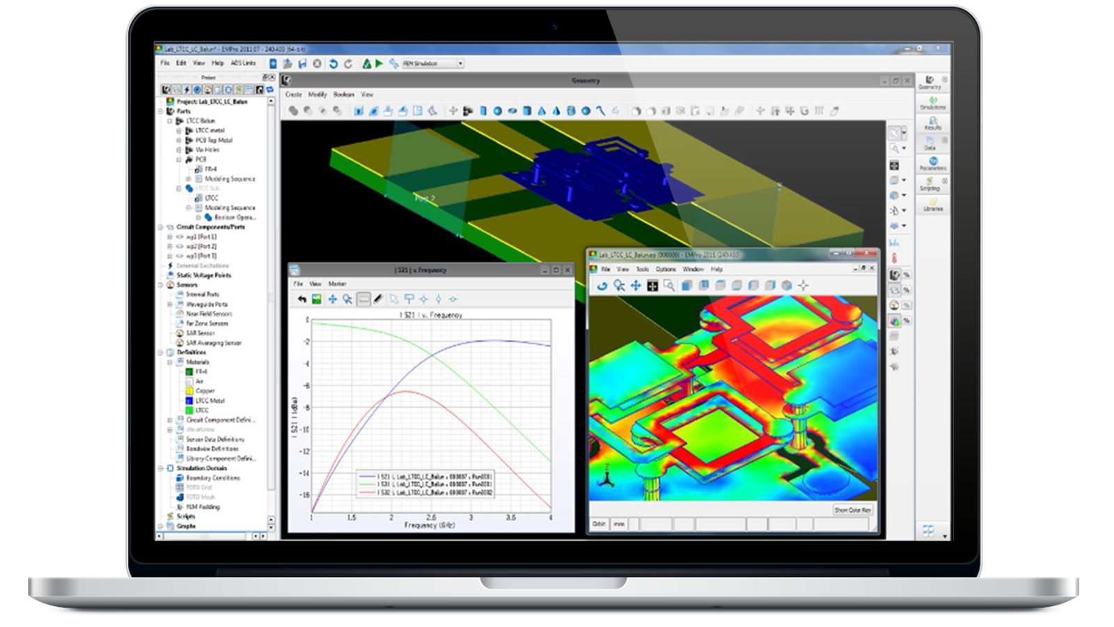
Electromagnetic circuit co-simulation eliminates the delay and potential errors introduced by a separate electromagnetic (EM) solver by running a 3D finite element model (FEM) simulation automatically in the same environment with easy automated setup and analysis. This process frees the RF circuit designer to perform 3D electromagnetic analysis and EM/circuit co-simulation iteratively in the design phase. Electromagnetic / circuit co-simulation yields an order of magnitude faster setup, giving you time to schedule other simulation tasks.
AI / machine learning (ML) can increase productivity and organizational efficiency by tailoring your electronic design automation (EDA) solutions into efficient workflows and interconnected design processes. Automation and application programming interface based workflows are a cornerstone of digital transformation. With Python application programming interfaces (APIs) for Keysight EDA tools, you can control data, simulators, platforms, and processes to engineer more predictable outcomes.
The continuous rise in substrate layer counts, smaller form factors, complex packaging technologies, and closer design proximities are factors that contribute to the increasing complexity of designs. Keysight ADS is the industry-proven multi-technology 3D layout and integrated EM-circuit co-simulation platform for designing RF modules that contain radio frequency integrated circuits (RFICs) , packaging, antennas, and RF printed circuit boards (PCBs).
Want help or have questions?