How to Test Regenerative Braking Power Systems

Measure Power Return During Regenerative Braking
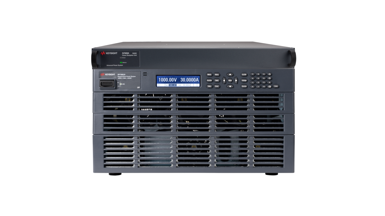
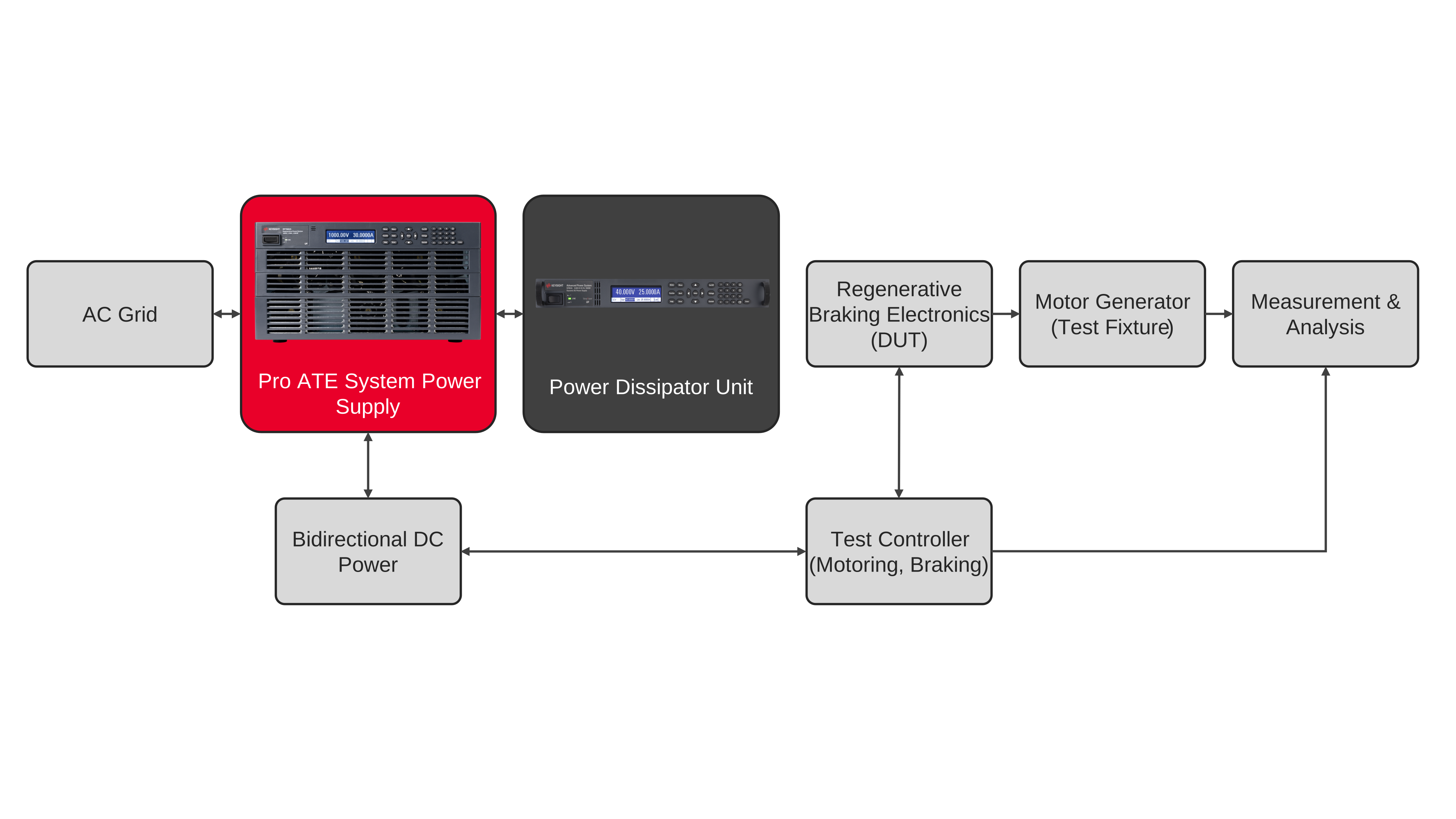
Regenerative braking testing at the battery-facing direct current (DC) interface requires a two-quadrant source, synchronized voltage and current acquisition, and a motor-generator test fixture that operates the device under test (DUT) through motoring and braking. Connect the regenerative power supply to the DUT’s DC interface and configure voltage-priority operation with positive sourcing and negative sinking current limits. Establish the programmed bus voltage, verify protection settings, and use the fixture controller to command the operating sequence. During motoring, the source supplies current to the DUT; during braking, it absorbs current returned through the power electronics. Keep each event within the source’s voltage, current, and power envelope. Time-align the operating command and electrical captures to identify the beginning and end of each braking interval.
For braking energy recovery, define positive current as flowing from the source into the DUT and negative current as returning from the DUT. Calculate instantaneous power from simultaneous voltage and current samples, then integrate the magnitude of negative power over each braking interval. Record recovered electrical energy, peak returned power, peak sinking current, maximum bus voltage, and recovery time to the specified voltage band. Repeat across specified bus voltages, braking commands, event durations, and repetition rates. Compare measurements against the DUT’s electrical limits and the approved test profile rather than assumed universal thresholds. Keep recovered energy at the DC interface separate from energy returned to the grid. Mechanical conversion efficiency requires additional torque and speed measurements and is outside this electrical measurement boundary.

Regenerative Braking Power Test Solution
See Block Diagram of Regenerative Braking Power Test Solution

Explore Products in Our Regenerative Braking Power Test Solution
-


![]()
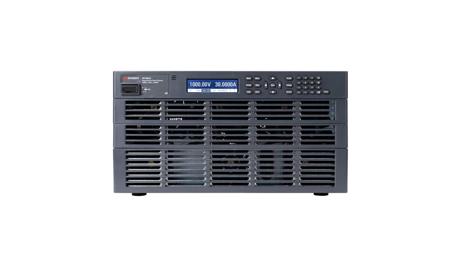
RP7982A Regenerative Power System 1000 V, ±90 A, 30 kW, 400/480 VAC
-

![]()
N7909A Advanced Power System — Power Dissipator Unit, 1,000 W


Discover Resources and Insights
Additional Resources for Regenerative Braking Power Test
Related Use Cases


-
![]()
Learn More
How to Test an Automotive Battery Management System
Automotive BMS test requires emulating the dynamic conditions of load and battery cells. Learn how to set up and test an automotive battery management system with a high-precision DC power supply.
Learn More

-
![]()
Learn More
How to Maximize Usable Power Output Range
Maximize usable DC power output across voltage ranges using autoranging power supplies for flexible and efficient DUT testing.
Learn More
-
![]()
Learn More
How to Scale Voltage and Current Outputs
Scale voltage or current output using auto-series and auto-parallel modes to meet diverse DUT requirements with a single power supply.
Learn More

Get in Touch with One of Our Experts
Need help finding the right solution for you?