How to Test DDR6 Transmitter Compliance

Automated DDR6 Transmitter Characterization
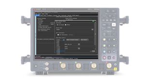
DDR6 transmitter testing begins by configuring the data rate, device organization, operating mode, and observation points for clock, command / address, data, and strobe signals. Accurate transmitter characterization requires controlled signal access and correction of the measurement path before device-level measurements can be performed. Engineers must characterize the probe, fixture, interconnect, and package paths and apply de-embedding to minimize the influence of the test environment. The acquisition must also isolate the intended read or write burst and establish the corresponding clock and strobe relationships before eye, timing, voltage, or jitter analysis begins. The test setup uses a 33 GHz real-time oscilloscope, an appropriate interposer or fixture, and low-loading probes to acquire signals with sufficient bandwidth and minimal loading. Burst identification can be performed using DQS-DQ phase relationships or command/address activity, helping ensure measurements are correlated with the correct memory transactions during characterization and compliance testing.
Once valid measurement conditions have been established, automated routines evaluate electrical, timing, eye-diagram, and jitter performance across the selected operating conditions while capturing characterization data, worst-case results, and numerical margin relative to applicable requirements. The software automates setup, execution, analysis, and reporting while retaining acquired waveforms for additional investigation and offline analysis. Automatic operating data-rate detection simplifies setup across multiple device configurations and speed grades, while de-embedding capabilities help remove fixture and interconnect effects from measurements. Equalization effects can also be evaluated together with decision feedback equalization (DFE) emulation so measurements reflect the configured operating state. Repeated trials support characterization across data rates, operating modes, devices, and test points, enabling correlation with pre-layout and post-layout simulation. The resulting workflow supports compliance assessment, margin analysis, debug, and transmitter characterization within a single software environment.

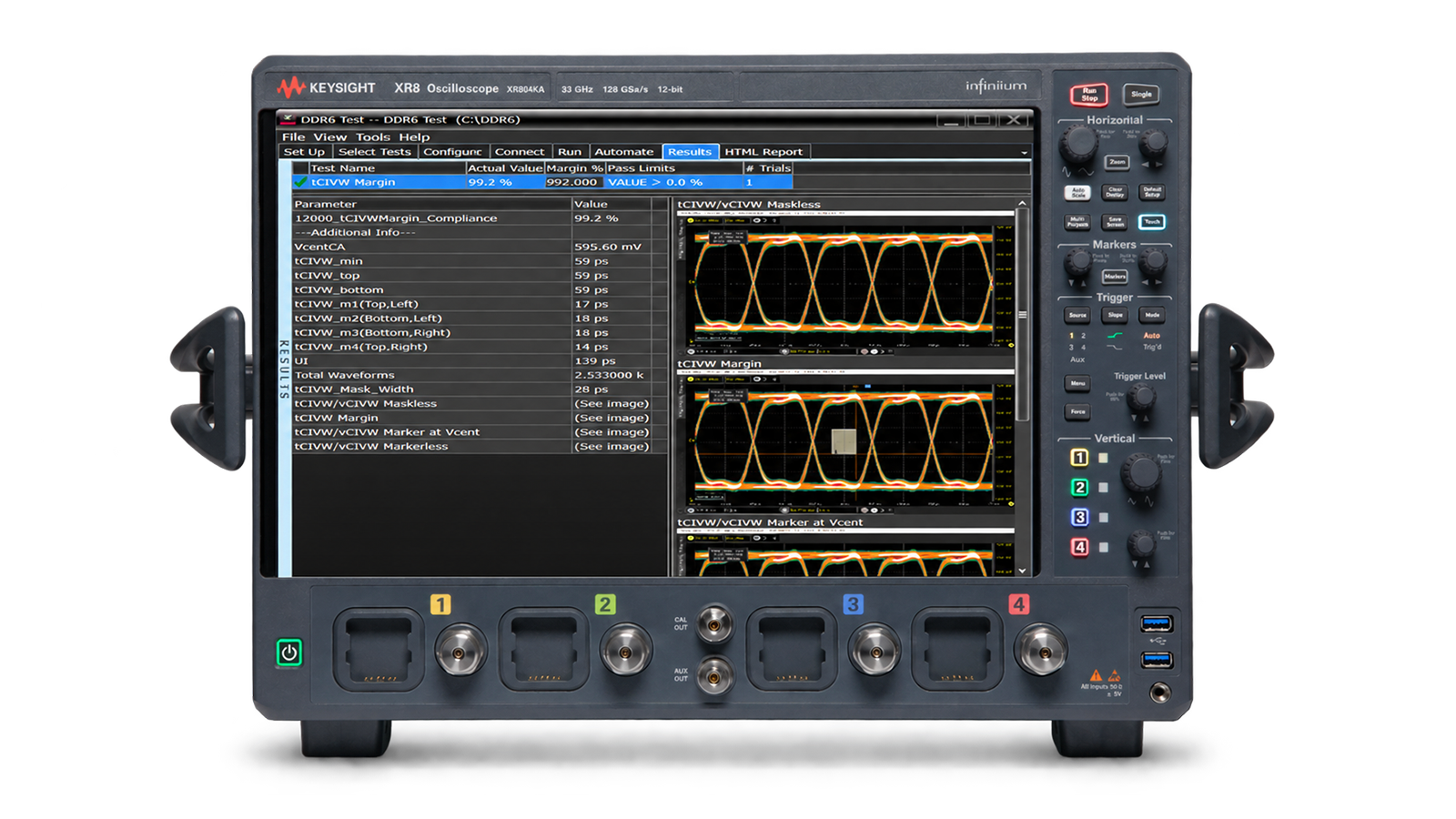
DDR6 Transmitter Compliance Test Solution
See Block Diagram of DDR6 Transmitter Compliance Test Solution


Explore Products in Our DDR6 Transmitter Compliance Test Solution
-


![]()
XR804KA Infiniium XR8 Oscilloscope: 8-33 GHz, 4 Channels
-

![]()
D9360DDRC Keysight Transmitter Compliance Test Software for DDR6


Discover Resources and Insights
Additional Resources for DDR6 Transmitter Compliance Test
Related Use Cases

-
![]()
Learn More
How to Validate GDDR7 Transmitter Compliance
Validate GDDR7 transmitter compliance with PAM3 eye diagram analysis, jitter measurement, and JEDEC-aligned mask testing.
Learn More

-
![]()
Learn More
How to Test PCIe 7.0 Transmitter Compliance
Learn how to test PCIe 7.0 transmitter compliance at 128 GT/s using PAM4 eye analysis, SNDR measurement, jitter decomposition, and automated validation workflows on high-bandwidth oscilloscopes.
Learn More
-
![]()
Learn More
How to Test USB 2.0 Interface Compliance
USB 2.0 compliance requires an oscilloscope with 2 GHz or higher bandwidth, a dedicated test fixture, and USB 2.0 compliance software. Learn how to test USB 2.0 compliance to ensure interoperability.
Learn More

Get in Touch with One of Our Experts
Need help finding the right solution for you?