What are you looking for?
CODE V
Optical design and ray tracing software to make better designs faster
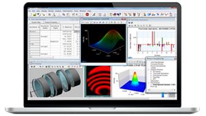
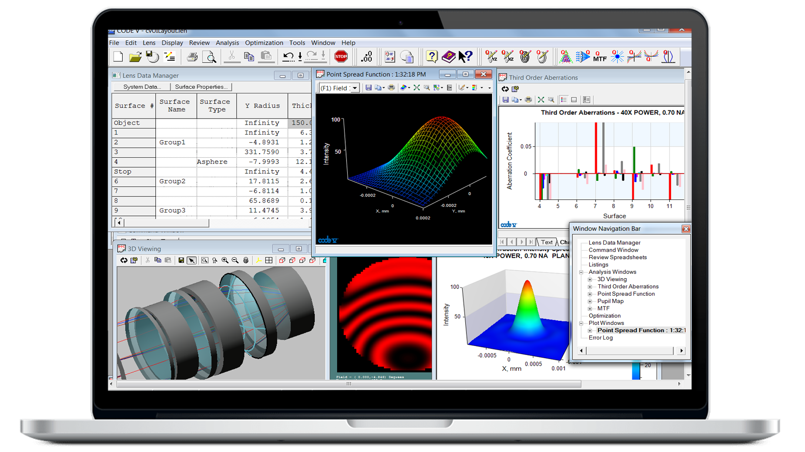
Achieve Ideal Optical Design Solutions with a Powerful Toolkit
CODE V optical design software empowers engineers to tackle optical design tasks with intuitive, intelligent tools to deliver better solutions faster. With accurate, built-in tolerancing, CODE V not only streamlines and accelerates optical designs, but also balances performance and manufacturing sensitivities to keep manufacturing costs low.
- Speed time to market with Global Synthesis design optimization.
- Get fast, accurate tolerancing for superior fabrication support.
- Maximize design performance and control manufacturing costs with AI-optimized glass selection features.
- Simulate and visualize optical system performance with fast 2D image simulation and comprehensive graphics capabilities, including 3D visualizations and diffraction-based image simulations.
- Easily model unusual systems with non-sequential surface modeling.
Analysis Tools for a High-Quality, Efficient Lens Design
Overcome your toughest lens design challenges with CODE V software. For example, when testing a zoomable cell phone lens design, use the CODE V spot diagram analysis tool to show the geometric size from a single point on the image. The image simulation tool can show how an image will look when taken from the cell phone lens. With extensive built-in libraries of optical system modules and many tools to design and simulate, you can save time on your optical engineering projects and boost productivity with CODE V.


Smarter Design Starts, Faster Tolerancing, Enhanced Simulation
CODE V 2026 introduces a set of new capabilities designed to accelerate starting‑point design, streamline complex tolerancing workflows, and improve image simulation and analysis.
- AI Start Expert
- Parallelized multicolor tolerancing
- Guided alignment setup
- Lens Performance Data file export
- Expanded image simulation accuracy
- New macros
Key Features of CODE V


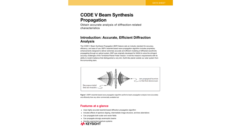
Beam Synthesis Propagation (BSP)
Achieve powerful, efficient diffraction analysis with BSP. Non-expert users can get expert results with minimal input, while advanced users have flexible control.
Read this blog article


Glass Expert
Speed up the design process by feeding your criteria into Glass Expert, which will automatically select the best set of glasses for your lens design.


Global Synthesis
Pick a ray-traceable point, select a merit function, and define constraints. Global Synthesis will deliver optimized solutions you can analyze and select.


Asphere design
Use Q-type polynomials to enable superior design optimization and tolerancing, which help ensure a cost-effective and manufacturable solution.


Image simulation
Get fast, accurate visual assessments of system image quality to communicate optical concepts and trade-offs during design evaluations.


Multi-environment coupling
Model and optimize athermalized spacer-based lens designs, considering refractive index and substrate changes due to temperature, pressure, and mounting variations.
Read this blog article
MetaOptic Design Module
Design meta optical surfaces with the CODE V MetaOptic Design add-on to significantly enhance the performance and functionality of traditional lenses.
- Enhance optical systems with advanced metalens technology.
- Apply intricate patterns of meta-atoms to surfaces using sophisticated meta-atom modeling.
- Use integrated tools to optimize metalens design and conventional refractive and reflective elements simultaneously.
Metalenses, like other diffractive elements, have the potential to become a powerful new tool in your optical engineering toolbox. With the MetaOptic Design module, you can combine ray tracing with electromagnetic field solvers to simplify imaging systems that include both conventional optics and metalenses.
Need Support for CODE V?
Featured Blogs

















Featured Resources








CODE V Optical Design Software – FAQ
CODE V is optical design software that provides engineers with intuitive, intelligent tools to deliver better solutions faster. With built-in features such as Global Synthesis, Beam Synthesis Propagation, and Glass Expert, along with accurate tolerancing and powerful design optimization, CODE V provides everything optical engineers need to design and simulate optical solutions.
Optical engineers use CODE V optical design software to model, analyze, optimize, and provide fabrication support for aerospace solutions, cameras, information display systems, microlithography, and photonics. More applications of CODE V include:
- Infrared spectrometers
- Segmented Cassegrain (mirror) telescopes
- Beam synthesis propagation of segmented mirror systems
- 3D visualization of a catadioptric system
- Stellar interferometers
- Coronagraphs
- Interferometric telescopes
- Cell phone lenses
- Panoramic video systems
- Fisheye and hyper-hemispherical fisheye lens simulation
- Zoom lenses
- Folded imagers
- Head-mounted displays with eye-tracking
- Lithography lens systems
Lens data
| Number of supplied lens models | 2400+, available via the New Lens Wizard or Patent Lens Search capability. |
| Number of surfaces | 990 |
| Number of wavelengths | 21 |
| Spectral weighting | Yes |
| Number of zoom positions | 99 |
| Number of zoomed parameters | 890 (most lens data can be zoomed) |
| Number of fields per zoom position | 25 |
| Number of MUL layers | 1,000 |
| Pupil specification options |
|
| Field specification options |
|
| Wide angle mode with ray input angle | Greater than 90 degrees |
| Vignetting factors | +/-Y and +/-X at entrance pupil, defined for each field point |
| Lens dimension options | Inches, mm, or cm |
| Afocal mode | Perfect lens conversion to an imaging system or true afocal modeling with field-independent accommodation |
| Aperture stop | Definable on any surface (chief ray iterated) |
| Chief ray specification | Can be specified to hit any surface at any location (default is center of stop) |
| Telecentric object | Yes |
| Number of through-focus positions | 18 |
| Environmental specifications |
|
| Surface types |
|
| Diffractive properties | Can be applied to any base surface:
|
| Radius specification | Radius or curvature |
| Radius solve types |
|
| Thickness solve types |
|
| Pickups | Yes (pickup from like or unlike parameters) |
| Glass types |
|
| Glass catalogs supplied | Hikari, Sumita, Pilkington, Schott, Ohara, Hoya, Corning France, Kodak, NSG, and "Special Materials" |
| Gradient index | Yes, several forms, including user-defined (via user-written subroutine) |
| Number of user-defined gradient coefficient | 150 |
| Glass property specifications | Specific gravity, transmittance, price, partial dispersion (for fictitious glass) |
| Refractive mode options |
|
| Mirror substrate specifications | Material, thickness, rear curvature |
| Aperture shapes | Circular, and/or rectangular, and/or elliptical |
| Aperture types | Clear aperture, obscuration, edge, hole |
| Aperture location on surface | Can be rotated and/or decentered |
| Aperture combinations | Multiple apertures allowed, can be ANDed or ORed (default is AND) |
| Decentrations/tilts | 3-D tilts or decentrations allowed on any surface (can be defined locally or globally) |
| Decentration/tilt types | Regular, reverse, decenter-and-return, bend, pure return |
| Non-sequential surfaces | Yes |
| Non-sequential elements (predefined) | Corner cube and roof |
| Refractive mode change | Yes, on specified hit number (up to two changes per surface) |
| Lens arrays | Yes, with uniform or user-specified spacings (all channels identical) |
| Surface coating options |
* Coating thickness variations also supported |
| Apodization options | Gaussian or user-defined (via FIL type interferogram file) |
| Surface deformation | Attached surface interferogram |
| Wavefront deformation | Attached wavefront interferogram (attached to a surface or to a pupil) |
| Polarization specifications |
|
| Polarization operators |
|
| Uniaxial crystal birefringent ray tracing | Yes |
| Intrinsic cubic crystal birefringent ray tracing | Yes |
| Stress birefringence modeling | Yes |
| Tolerance types | Many forms (single surface and surface groups) |
| Number of tolerances | Unlimited |
| Compensator types | Any tolerance can be a compensator |
| Number of compensators | Unlimited |
| Interferogram types |
|
| Interferogram locations | Any surface or pupil |
| Interferogram orientation | Can be scaled, decentered, rotated, or flipped in X or Y |
| User-defined features (via user-written subroutines) |
|
Lens operations
| Scale lens | Yes (many variations) |
| Flip surfaces | Yes, in X or Y |
| Copy surfaces | Yes (from current or stored lens) |
| Copy zoom position data | Yes (can insert/delete individual zoom positions too) |
| Automatic data setting |
|
| Environmental scaling | Yes, for temperature and pressure, including radial thermal gradients |
System display options
| OpenGL 3D rendering | Yes, includes mouse interaction |
| Line drawings | Yes, profiles, slices, perspective views |
| Lens element drawings |
|
| Tabular output | Complete listing of all model information |
Optimization
| Number of optimization targets | Unlimited |
| Number of variables | 999 |
| Number of variables plus constraints | 10,000 |
| Number of coupled components | 700 |
| Number of groups | 40 |
| Number of components in groups | 80 |
| Local optimization method | Damped least squares |
| Global optimization method | Global Synthesis (unique algorithm) |
| Constraint handling |
|
| Constraint type categories |
|
| Optimization controls | Yes, many optional controls to impact convergence; ray grid definition, field, pupil, and wavelength weighting |
| Error function types |
|
| Automatic test plate fitting | Yes |
| Cam calculation for zoom lenses | Yes |
Application programming interface
| COM support | Yes |
Image analysis options
| Diagnostic analysis options |
|
| Geometrical analysis options |
|
| Diffraction analysis option |
|
| Illumination analysis | Yes |
Tolerancing, fabrication support, and system analysis options
| Tolerancing options |
|
Fabrication support options |
|
| System analysis options |
|
Macro-PLUS
| Number of variables | Unlimited |
| Variable types | Numeric and string |
| Arrays | 1 or 2 dimensions (unlimited size) |
| Branching | IF, ELSE IF, GOTO |
| Loops | FOR, UNTIL, WHILE |
| Built-in functions |
|
| Input/Output | Read/write (formatted or unformatted) |
| File interface | Read, write, append (ASCII files) |
| Lens database access | Yes |
| Spreadsheet capability | Yes (Worksheet Buffer™) |
| Macro library | Over 100 macros supplied |
Product support
| License terms | Monthly or annual lease |
| Technical support | Included at no extra cost |
| Software updates | Included at no extra cost |
| Documentation updates | Included at no extra cost |