How to Measure Peak-to-Average Power Ratio in Modulated Signals

Characterize Signal Envelope Variations
Digitally modulated radio frequency (RF) signals can exhibit substantial differences between their instantaneous peak power and average power. This relationship is commonly expressed as the peak-to-average power ratio (PAPR), which provides useful information about the signal's power distribution and the demands it places on RF transmitters, amplifiers, and other components. A high peak-to-average ratio can require additional transmitter back-off and can affect how efficiently an RF power amplifier operates. Engineers therefore need to measure both peak and average power under the same signal conditions to determine the ratio accurately.
The measurement setup includes a peak and average power sensor connected to a compatible power meter and the modulated RF signal under test. Engineers establish the operating frequency and signal level, configure the appropriate measurement settings, and acquire peak and average power measurements from the same signal. The resulting values can be compared to evaluate PAPR across different modulation conditions or operating states. This workflow supports characterization of digitally modulated transmitters and RF components where understanding the relationship between peak and average power is important for evaluating power handling and transmitter performance.

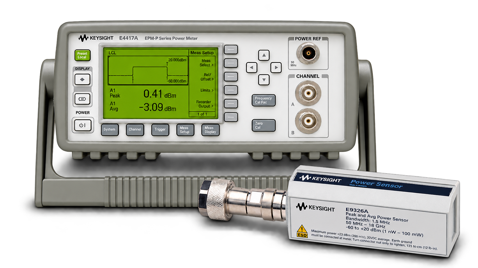
Peak-to-Average RF Power Measurement Solution
See Block Diagram of Peak-to-Average RF Power Measurement Solution


Explore Products in Our Peak-to-Average RF Power Measurement Solution
-

![]()
E9326A Peak and Average Power Sensor, 50 MHz - 18 GHz, 1.5MHz Bandwidth
-

![]()
E4417A EPM-P Series Dual-Channel Power Meter


Discover Resources and Insights
Additional Resources for Peak and Average RF Power Measurements
Related Use Cases

-
![]()
Learn More
How to Perform Burst Power Measurement
Measure burst RF signal power using time-gated averaging with power meters, sensors, and automated control software for TDMA systems.
Learn More

-
![]()
Learn More
How to Measure RF Power During Rapid Amplitude Switching
Measure RF power during rapid amplitude transitions using a power meter, fast-response sensors, continuous acquisition, and automated measurement techniques.
Learn More
-
![]()
Learn More
How to Measure Average Power of Frequency-Hopping Signals
Measure average RF power of frequency-hopping signals using power meters, sensors, and time-aligned measurement techniques for accurate results.
Learn More

Get in Touch with One of Our Experts
Need help finding the right solution for you?