


Choose a country or area to see content specific to your location
What are you looking for?
Bridging design and physical testing to evaluate drop, impact, shock, and vibration compliance before hardware exists.
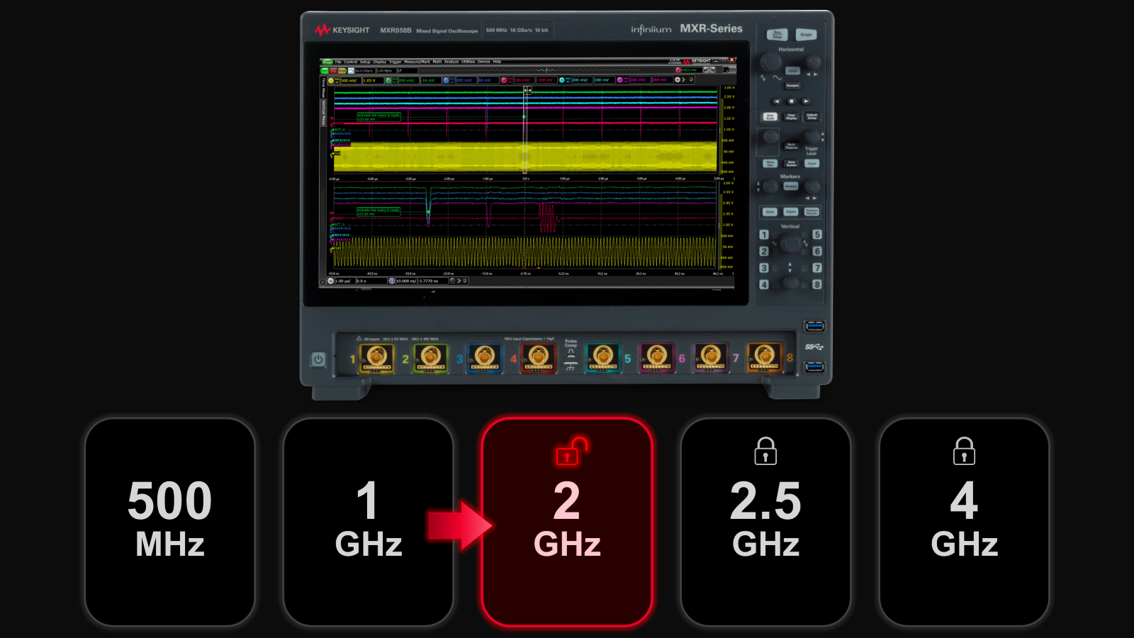
Unlock your free upgrade to the next bandwidth tier.
Strengthen 1.6T network reliability for AI-scale workloads from transceivers to interconnects.
Pair Keysight VSA software with the new XA5 signal analyzer for advanced visualization, demodulation, and analysis — start your 30-day trial today.
With extra memory and storage, these enhanced NPBs run Keysight's AI security and performance monitoring software and AI stack.
Explore end-to-end workflows spanning IC design, validation, wafer test, and photonics.
Explore curated support plans, prioritized to keep you innovating at speed.
Achieve 200+ Gbaud multi-level modulated signals with high-speed AWGs for digital and optical standards.
Maximize accuracy and performance with precision accessories engineered for Keysight instruments.
Explore dual-channel and ultra-wideband signal analysis for demanding RF workflows.
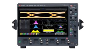
Get faster, clearer insights with our new multicore, 12-bit oscilloscope up to 33 GHz. Trade in your old oscilloscope and get credit toward a new XR8.
Purpose-built solutions engineered for the design and test challenges unique to your industry.
Use Cases mapped to every stage of your product lifecycle, from design through operations.
Success Stories
Authoritative application notes, data sheets, reference designs, and test procedures to accelerate design and validation decisions.
Hands‑on bootcamps that teach system design, test methods, and production workflows engineers can apply immediately.
Learning Hub
Explore methodologies, test strategies, and technical resources for designing, validating, and scaling AI systems and networks.
Quick access to support related self-help tasks.
Additional content to support your product needs.
Explore services to accelerate every step of your innovation journey.
Precise power control for optical signal testing
Keysight optical attenuators provide precise control of optical signal power for accurate and repeatable optical component testing. Attenuators emulate signal loss, balance power levels, and protect sensitive devices during testing. Keysight attenuators offer low insertion loss, low polarization-dependent loss (PDL), and high resolution across a wide attenuation range. These features ensure accurate and stable signal control in both single-mode and multimode applications. Select the optical attenuator you need to simulate real-world optical link conditions, calibrate power levels, or automate signal conditioning in your optical test setup based on maximum attenuation and number of channels. Choose one of our popular configurations or configure one specific to your application.
Offers fine control across a broad range up to 60 dB, enabling accurate signal loss emulation for diverse optical power levels and test scenarios.
Rapid attenuation adjustment improves test throughput and responsiveness for automated applications with quick signal level changes.
Delivers highly repeatable attenuation settings over thousands of cycles, supporting stable, automated test setups and long-term use in manufacturing environments.
Minimizes polarization-dependent loss to ensure consistent and accurate attenuation across varying signal polarizations, ideal for precision testing of sensitive optical components.
Maximum attenuation
35 dB to 60 dB
Number of channels
1 to 4
Insertion loss
< 1.7 dB to <2.2 dB
Power range
+20 dB to -50 dB, +20 dB to -35 dB
Fiber mode
Single-mode, Multimode
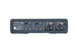
N7752C
The N7752C two-channel variable optical attenuator for single-mode fiber enables highly efficient optical transceiver and network integration testing. It is equipped with two additional, independent optical power meters and based on electrically controlled variable optical attenuator (VOA) modules.
Power Setting and Control Modes
In power setting mode, which is available on all N77-C variable optical attenuators, the power level at the attenuator output is set. The N7752C uses the feedback signal from a photodiode after a monitor tap to control the desired power level at the optical output. When power control is active, the instrument also automatically corrects for power changes at the input so that the output power level you set is maintained with ±0.02 dB typical repeatability.
The N7752C’s additional power meters can be used to measure the absolute power level from an external fiber to calibrate the offset from the attenuator’s output monitor, to correct for external insertion loss, like from connections, switches and couplers. Equipped with an analog voltage output, they can provide feedback for automated alignment applications, either linearly or logarithmically proportional to the optical power level. The new logarithmic mode is very helpful for tracking the signal level over a wide dynamic range, such as during probe adjustment.
Attenuation setting mode
In attenuation mode, the calibrated value of attenuation in dB is set directly, without use of the power monitor. This supports use with legacy software written for attenuators without power monitors or when the power monitor reading is impaired, as due to modulation or from a signal at another wavelength or in the reverse direction.
Advanced control of power change
Especially for testing devices that are sensitive to rapid power changes, the rate of change can be set on the instrument and applies to the attenuation mode. The N7752C can be set from 0.1 to 1000 dB/s. New with the N77-C attenuators is the ability to program a ramp of attenuation steps, including dwell time at each step, which can be either stepped automatically or synchronized with an external trigger. Trigger outputs are also available. This new functionality can be used instead of sending individual program commands for each step and aid in efficient synchronization with other instruments. In power control mode, during attenuation sweeps, as well as when activating the shutter mode, 1000 dB/s change rate is applied.
Calibration offsets for external losses
Comprehensive offset functionality allows you to calibrate the optical path in various test set-ups. There is an offset for the attenuation factor, and an independent offset for the output power level, to calibrate for losses due to patch cords, connectors, and switches. Additionally, wavelength and offset value pairs can be stored in a table to compensate for wavelength-dependent effects in the optical path of the set-up. This allows you to precisely set the optical power level directly at the input interface of your device under test.
With the extra optical power meter channel of the N7752C, calibration is even easier and more convenient. All power related offsets can be determined by a firmware function that reads a value from the reference power meter. The difference between the power value read by the reference power meter and the actual value of the attenuator is automatically stored as the offset.
New user attenuation-mode calibration
To calibrate the attenuation setting mode for a chosen source wavelength, a new self-calibration has been implemented. The calibration process, executed at the chosen wavelength and power higher than 0 dBm, and with the setup kept stable, will run for about 2 minutes. For using the attenuator at a different wavelength, the user calibration can be disabled, or the calibration can be executed at the new wavelength. The calibration data can be reenabled after a preset or reboot, or the configuration can be saved with enabled calibration.
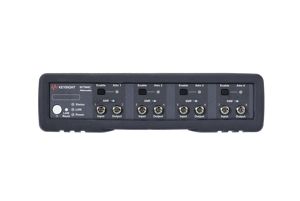
N7764C
The N7764C four-channel variable optical attenuators for single-mode fiber enables highly efficient optical transceiver and network integration testing. It is based on electrically controlled variable optical attenuator (VOA) modules.
In power setting mode, which is available on all N77-C variable optical attenuators, the power level at the attenuator output is set. The N7764C uses the feedback signal from a photodiode after a monitor tap to control the desired power level at the optical output.
When power control is active, the instrument also automatically corrects for power changes at the input so that the output power level you set is maintained with ±0.02 dB typical repeatability.
In attenuation mode, the calibrated value of attenuation in dB is set directly, without use of the power monitor. This supports use with legacy software written for attenuators without power monitors or when the power monitor reading is impaired, as due to modulation or from a signal at another wavelength or in the reverse direction.
Especially for testing devices that are sensitive to rapid power changes, the rate of change can be set on the instrument and applies to the attenuation mode. The N7764C can be set from 0.1 to 1000 dB/s. New with the N77-C attenuators is the ability to program a ramp of attenuation steps, including dwell time at each step, which can be either stepped automatically or synchronized with an external trigger. Trigger outputs are also available. This new functionality can be used instead of sending individual program commands for each step and aid in efficient synchronization with other instruments. In power control mode, during attenuation sweeps, as well as when activating the shutter mode, 1000 dB/s change rate is applied.
Comprehensive offset functionality allows you to calibrate the optical path in various test set-ups. There is an offset for the attenuation factor, and an independent offset for the output power level, to calibrate for losses due to patch cords, connectors, and switches. Additionally, wavelength and offset value pairs can be stored in a table to compensate for wavelength-dependent effects in the optical path of the set-up. This allows you to precisely set the optical power level directly at the input interface of your device under test.
To calibrate the attenuation setting mode for a chosen source wavelength, a new self-calibration has been implemented. The calibration process, executed at the chosen wavelength and power higher than 0 dBm, and with the setup kept stable, will run for about 2 minutes. The calibration data can be reenabled after a preset or reboot, or the configuration can be saved with enabled calibration.
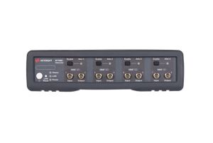
N7768C
The N7768C is a four-channel power-monitored optical attenuator for multimode fiber applications. Its bulk-optic filter and collimated beam path is designed to assure homogeneous attenuation of all input modes. It maintains the beam profile of signals that comply with the encircled flux conditions of IEC 61280-4-1. Speed, compactness and optical quality are optimized for manufacturing test.
Optical attenuator instruments are used to flexibly control optical signal power levels in test setups. A primary application is determining optical receiver sensitivity by measuring the BER vs. input signal power. The N7768C provides 4 attenuator channels for 50 µm/ OM3 multimode fiber setups.
For dependable multimode transceiver testing, the instrument used to set the power level should not change this modal distribution. The bulk-optic filter and collimated beam path of the N7768C multimode attenuator is designed to assure homogeneous attenuation of all input modes. It maintains the beam profile of signals that comply with the encircled flux conditions of IEC 61280-4-1.
The output power is monitored, especially to allow accurate and stable power setting independent of the input power. Convenient offset parameters allow the set power to correspond to the signal after other optical components in the setup path.
Innovate at speed with curated support plans and prioritized response and turn-around times.
Get predictable, lease-based subscriptions and full lifecycle management solutions—so you reach your business goals faster.
Experience elevated service as a KeysightCare subscriber to get committed technical response and more.
Ensure your test system performs to specification and meets local and global standards.
Make measurements quickly with in-house, instructor-led training, and eLearning.
Download Keysight software or update your software to the newest version.
An optical attenuator is a device used to reduce the power of an optical signal in a controlled, repeatable way. In test setups, it's essential for emulating signal loss, balancing power levels across channels or paths, and protecting sensitive receivers or components. By mimicking real-world link conditions, optical attenuators help ensure components perform reliably in actual deployments.
Use an optical attenuator whenever you need to:
Attenuators are widely used in R&D labs, system validation, and production environments for both passive and active optical components.
When selecting an optical attenuator for your test setup, consider the following key specifications to ensure it meets your application requirements:
Additional important specs may include polarization-dependent loss (PDL) for sensitive testing, repeatability for automation, and switching speed for dynamic test scenarios. Matching these parameters to your testing environment helps ensure reliable, accurate results.
Polarization-Dependent Loss (PDL) refers to variations in attenuation based on the polarization state of the signal. In precision testing, especially for coherent or polarization-sensitive components, low PDL ensures consistent results regardless of signal polarization. This is especially important when characterizing modulators, transceivers, and photonic integrated circuits.