How to Perform PV Inverter Testing

Simulating PV arrays to test MPPT algorithms and circuits
Testing PV inverters requires engineers to verify the performance of the inverter’s maximum power point tracking (MPPT) algorithms and circuits. MPPT algorithms are complex, and under-the-sun testing at different temperatures and irradiance conditions is difficult, expensive, and time-consuming. The engineers also need to load and measure the output power of the PV inverter.
Escape the unpredictability of local weather conditions by using a PV / solar array simulator. Use a programmable DC power source to help simulate real-world PV / solar arrays, and test them against various environmental factors such as temperature, irradiance, age, and cell technology. Make sure to test the inverters according to the industry standards, such as EN50530, which provides a procedure for measuring the efficiency of MPPT. Use an AC / grid emulator to load and test the inverter’s output.
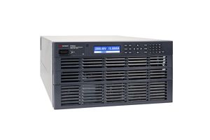
PV inverter test solution
See demo of the PV inverter test
Explore products in our PV inverter test solution
-

![]()
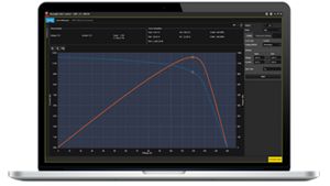
DG8901A License For Automated EN50530 Static and Dynamic MPPT Efficiency Testing
-

![]()
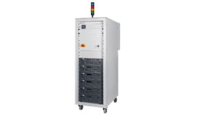
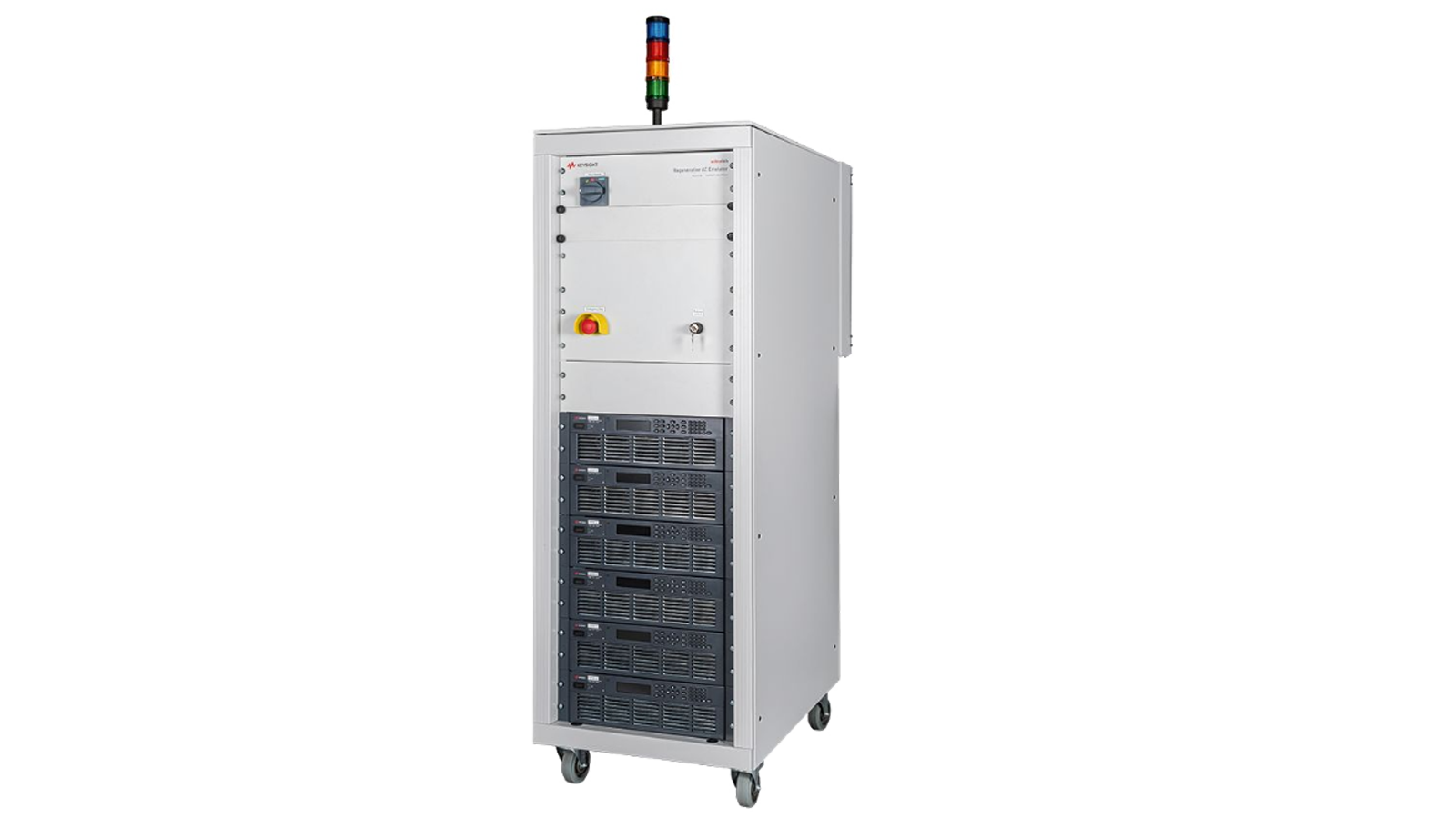
SL1213A Scienlab Regenerative AC Emulator, 1200 VAC, 65 A, 90 kVA, 3‑Phase
-
![]()
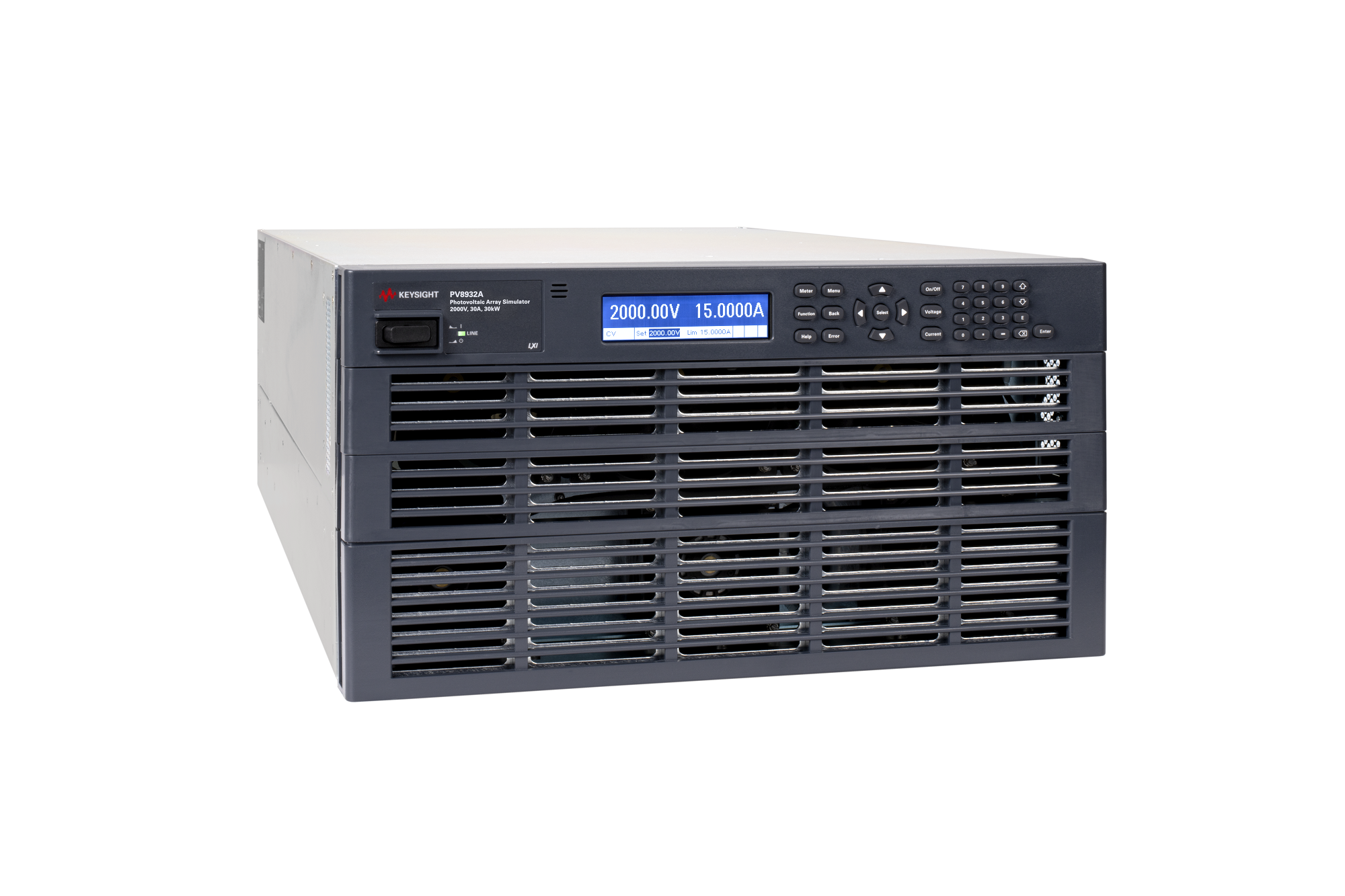
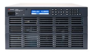
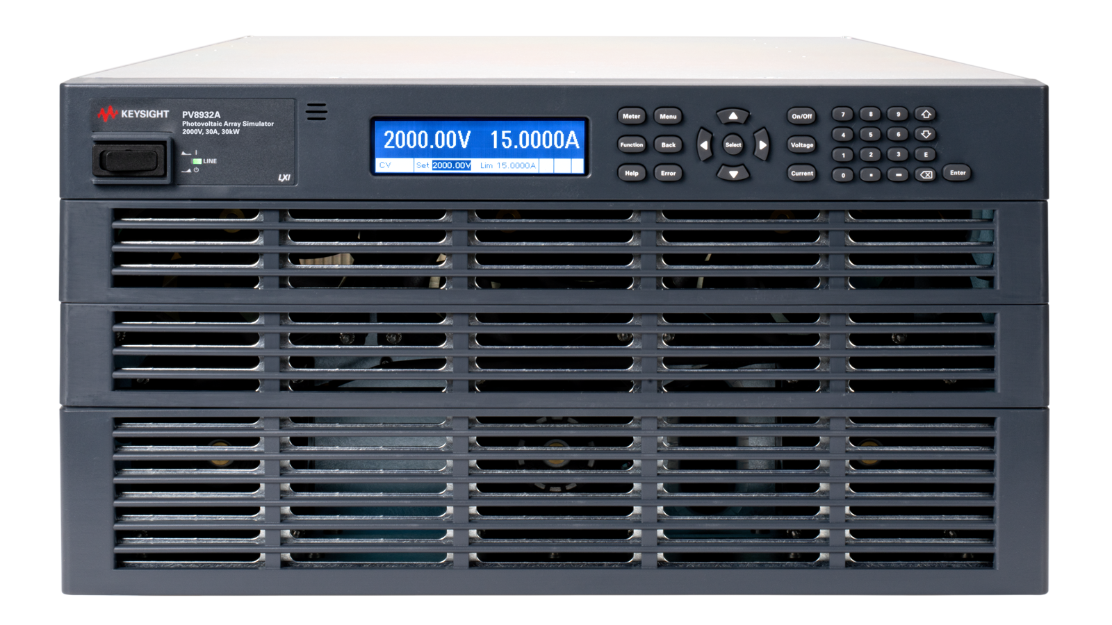
PV8932A Photovoltaic Array Simulator, 2000 V, 30 A, 30kW, 400/480 VAC
-
DG9112A Advanced Photovoltaic 12-Input Inverter Test Software



Discover resources and insights
Additional resources for PV inverter testing
Related use cases


-
![]()
Learn More
How to Perform Accurate In-Fixture VNA Measurements
An in-fixture vector network analyzer (VNA) measurement connects a device under test (DUT) through a test fixture rather than directly to the analyzer test ports. The measurement setup consists of a vector network analyzer, calibrated test cables, fixture interfaces, and a repeatable DUT connection. The procedure begins with calibration at accessible measurement reference planes, followed by fixture characterization and the application of appropriate error-correction or de-embedding techniques. Engineers then measure the DUT's scattering parameters (S-parameters) across the required frequency range to evaluate insertion loss, return loss, and other relevant RF characteristics while accounting for the electrical effects introduced by the test fixture.
Learn more

-
![]()
Learn More
How to Validate O-RAN Radio Unit Synchronization
Validate O-RAN Radio Unit Synchronization: a technical workflow for configuring clock references, measurement interfaces, and controlled network conditions. Review how to capture synchronization behavior, interpret clock-quality and protocol observations, and compare results with explicitly selected timing or conformance criteria. This workflow is intended for engineering validation of connected Ethernet and O-RAN equipment.
Learn more
-
![]()
Learn More
How to Select VNA Calibration Standards
A vector network analyzer (VNA) calibration setup uses a defined set of calibration standards and their associated electrical characteristics to establish accurate measurement reference planes. The procedure begins by identifying the connector interface, reference impedance, frequency range, and appropriate calibration method. Engineers select compatible calibration standards and perform the required calibration sequence to correct systematic measurement errors, including directivity, source and load match, and reflection and transmission tracking. After calibration, verification measurements are performed using an independent verification standard or a device with known characteristics. The results are compared against expected values to assess calibration accuracy before proceeding with scattering parameter (S-parameter) measurements of the device under test.
Learn more


-
![]()
Learn More
How to Automate MultiGBASE-T1 Receiver Compliance Testing
Automate MultiGBASE-T1 receiver compliance testing under IEEE 802.3ch with coordinated instrument control, BER verification, repeatable test execution, and results reporting.
Learn more
-
![]()
Learn More
How to Characterize Receivers Across Worst-Case Channels
Evaluate MultiGBASE-T1 receiver BER performance under controlled test conditions across representative automotive Ethernet channel configurations. Examine how cable and interconnect characteristics affect signal integrity and receiver performance.
Learn more
-
![]()
Learn More
How to Debug CAN FD and CAN XL Signals
Debug CAN FD and CAN XL signals using an Expert Benchtop Oscilloscope, automotive protocol triggering and decoding software, and differential probing to examine arbitration and data-phase behavior, correlate decoded frames with physical-layer waveforms, and troubleshoot high-speed automotive communication.
Learn more

Get in touch with one of our experts
Need help finding the right solution for you?