How to Integrate RF Power Measurements into Automated Test Systems

Integrate Power Measurements into Automated Test
Integrating radio frequency (RF) power measurements into an automated test system requires coordinating measurement configuration, acquisition timing, instrument communication, and result handling within the test sequence. A USB power sensor provides a direct digital interface between the radio frequency measurement point and the test-system controller without a separate power meter. Engineers can incorporate average power measurements into automated test operations while maintaining programmatic control of measurement settings and acquisition. This architecture is useful when power verification becomes part of a functional, validation, or manufacturing test sequence rather than an isolated bench measurement.
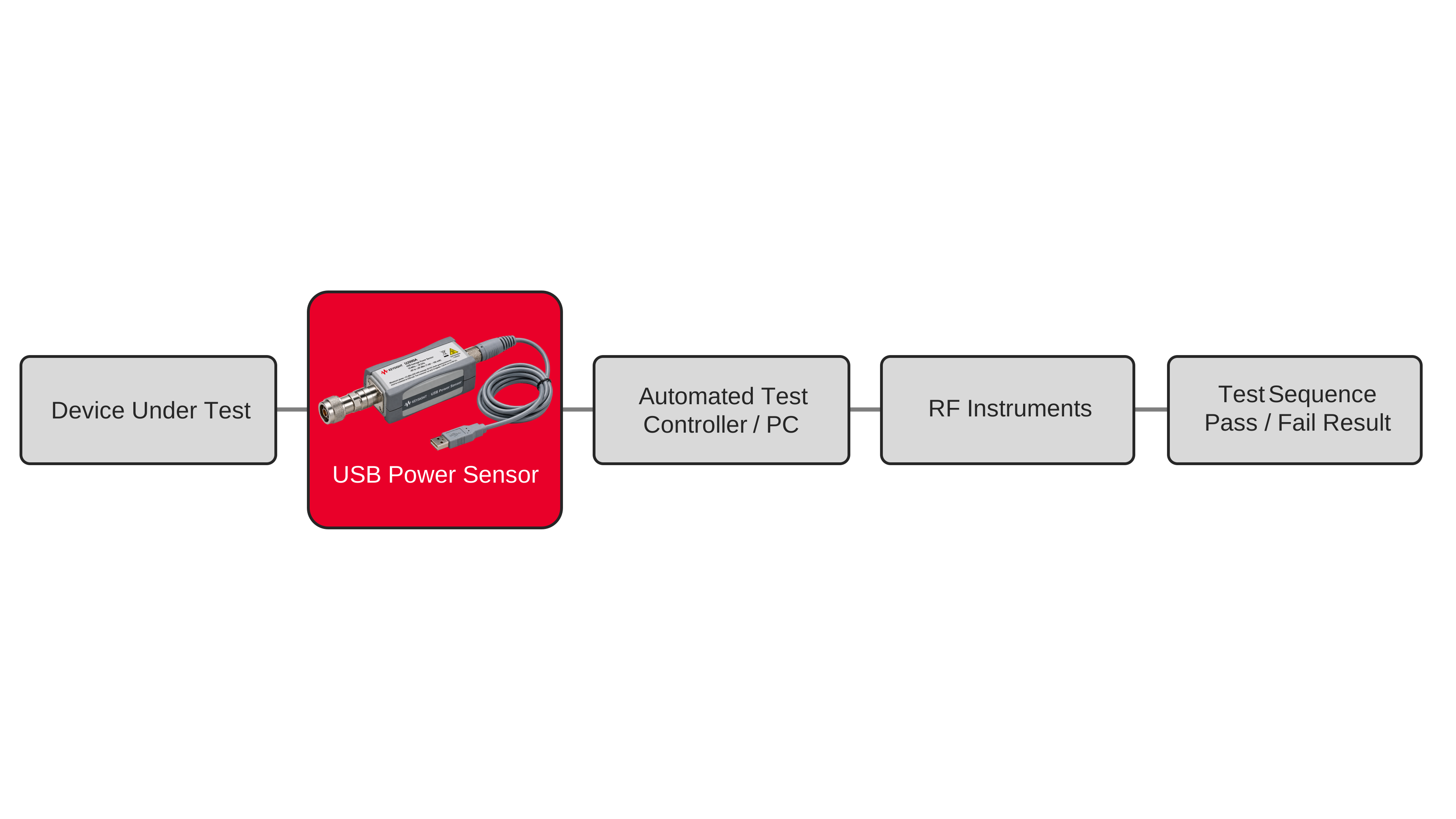
The measurement configuration typically includes the device under test, a USB power sensor, a host computer or test-system controller, and any additional instruments required by the automated test. Engineers establish the radio frequency connection, perform zeroing as required, configure acquisition settings, and coordinate measurements using internal or external triggering when timing must align with other test events. Standard Commands for Programmable Instruments (SCPI) can be used to control the sensor, initiate measurements, retrieve results, and incorporate power readings into automated pass/fail logic, data storage, or subsequent test operations.

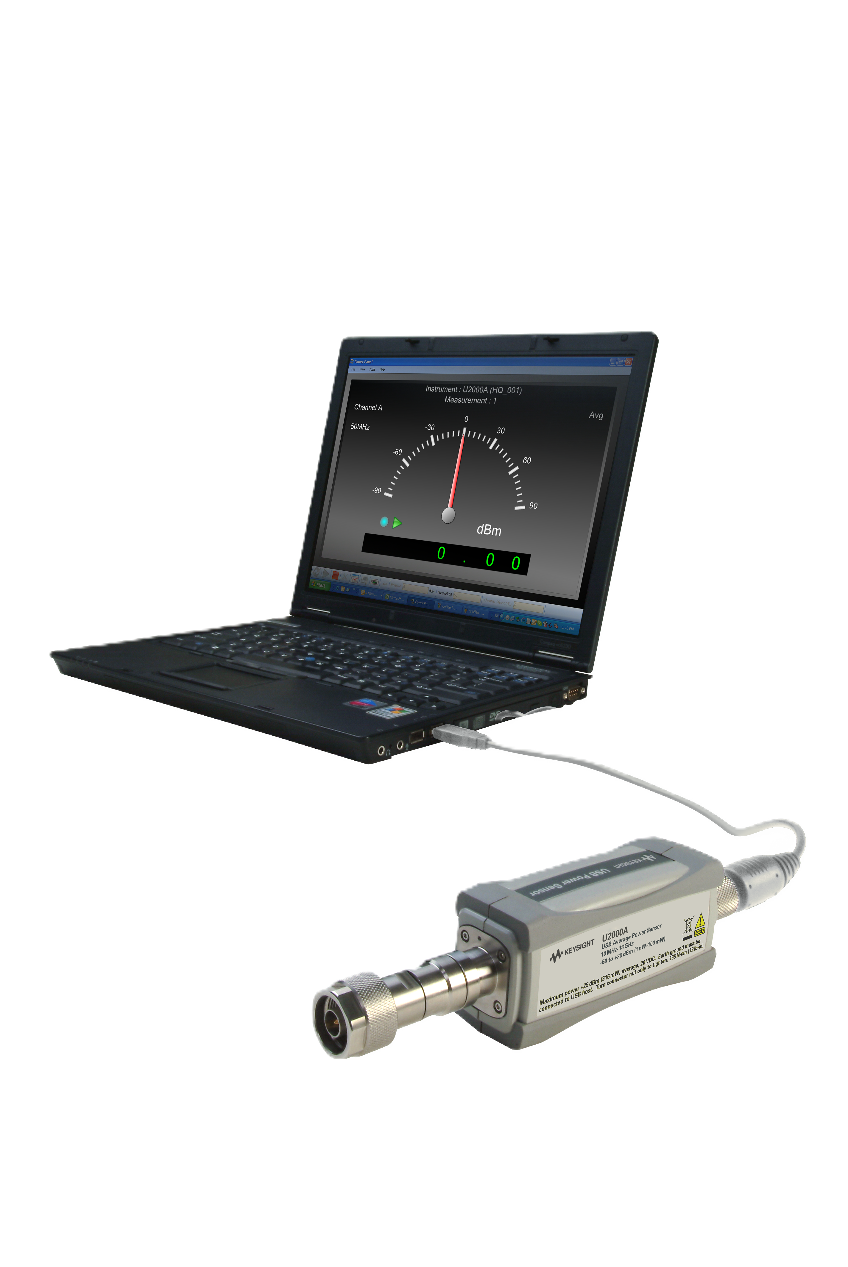
Automated RF Power Measurement Solution
See Block Diagram of Automated RF Power Measurement Solution

Explore Products in Our Automated RF Power Measurement Solution
-

![]()
U2000A 10 MHz - 18 GHz USB Power Sensor


Discover Resources and Insights
Additional Resources for Automated RF Power Measurements
Related Use Cases


-
![]()
Learn More
How to Automate Multi-DUT RF Power Calibration
Automate RF power calibration workflows across multiple devices using a power meter, sensors, and software for repeatable and efficient measurements.
Learn More

-
![]()
Learn More
How to Extend Diode Power Sensor Life in Production Test Environments
Extend diode power sensor life in production test environments using proper handling practices, controlled connections, and peak power monitoring.
Learn More
-
![]()
Learn More
How to Reduce RF Test Cycle Time Using Diode Power Sensors
Reduce radio frequency test cycle time using diode power sensors, fast-response power measurements, and automated measurement workflows to improve production and bench test efficiency.
Learn More

Get in Touch with One of Our Experts
Need help finding the right solution for you?