
N1081PLCA PCI Express PLL Measurement Software Application
Data Sheets
Introduction
The Keysight N1081PLCA PLL Test Application leverages FlexPLL software (a new feature in N1010300A Signal Integrity SW package) to perform fast, accurate and repeatable measurements of phase-locked loop (PLL) bandwidth and peaking.
PLL bandwidth and peaking measurements are performed on a Jitter Transfer Function (JTF) response. Characterizing the JTF response is a stimulus-response measurement. A precision jitter source, such as the Keysight M8000 Series BERT, can be combined with a jitter receiver such as the N107x Clock Recovery Solution or N1060A Precision Waveform Analyzer module, to create an accurate PLL stimulusresponse measurement system.
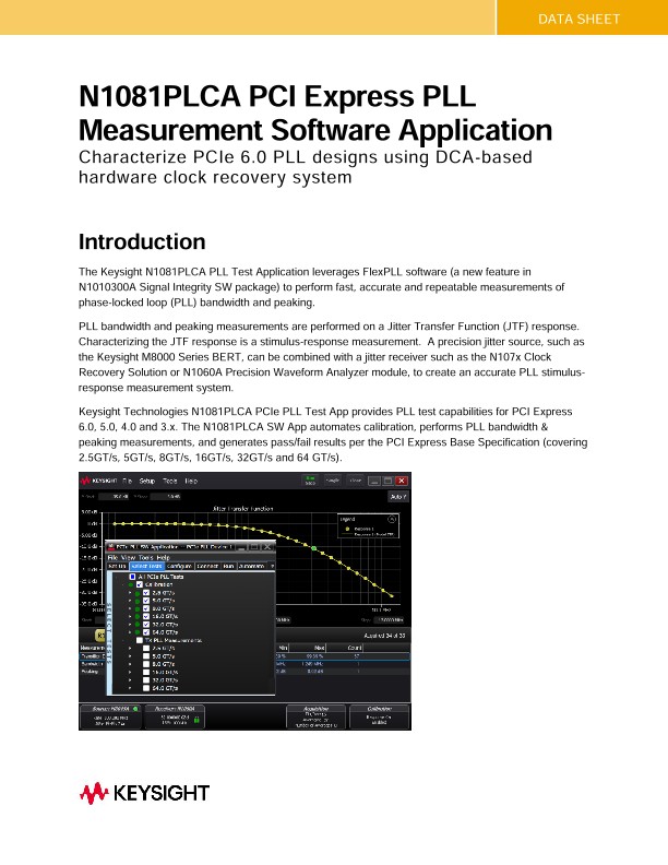
Keysight Technologies N1081PLCA PCIe PLL Test App provides PLL test capabilities for PCI Express 6.0, 5.0, 4.0 and 3.x. The N1081PLCA SW App automates calibration, performs PLL bandwidth & peaking measurements, and generates pass/fail results per the PCI Express Base Specification (covering 2.5GT/s, 5GT/s, 8GT/s, 16GT/s, 32GT/s and 64 GT/s).
Clock Recovery Basics – Why are PLL Bandwidth and Peaking Important?
PLLs are used throughout today’s high-speed digital systems, and one common application for a PLL is in clock recovery circuits. The clock recovery circuit is used in receivers to recover a clock from the incoming data, and the recovered clock is then used to sample the incoming data. In addition to recovering a clock, the clock recovery circuit is instrumental in controlling how much jitter will appear on the recovered clock. As a result, the PLL circuit plays a critical role in managing system jitter.
The response of the PLL is known as the jitter transfer function, or JTF. It is essentially a low-pass filter that controls how of the jitter on the incoming data signal is passed to the recovered clock (output). The Observed Jitter Transfer Function (OJTF) is simply 1-JTF in real and imaginary terms. Most Standards specify PLL performance in terms of loop order (determines response roll-off in dB/decade), 3dB bandwidth, and peaking. These PLL parameters can be measured using the Jitter Transfer Function
Characterizing a Jitter Transfer Function
Characterizing a Jitter Transfer Function (JTF) is a stimulus – response measurement. Using a jitter source, we inject known Periodic Jitter (PJ) components (amplitude and frequency) and then measure the injected PJ component using the DCA-based jitter receiver.
There are two steps to the JTF measurement:
1. Calibration – characterize the measurement system without DUT. This establishes a “baseline” for subsequent measurements. The calibration is performed once for a particular setup, and the same calibration can be used to test multiple DUTs so long as the setup and test conditions do not change.
2. Measurement – Insert DUT between the source and receiver and measure the JTF