
NS1-Class Expert ATE System DC Power Supply
Datenblätter.
Keysight DP5700 Series Programmable DC Power Supplies
The Keysight DP5700 Series programmable DC power supplies provide compact, high-density power for laboratory and automated production test systems. The series includes 92 single-output model configurations across nominal power levels of 1.5 kW, 3.4 kW, 5 kW, and 7.5 kW. Engineers can select a model based on output voltage, current, AC input requirements, and available rack space.
This data sheet describes the DP5700 Series electrical specifications, supplemental characteristics, control features, connectivity, and accessories. It also explains model suffixes, parallel and series configurations, mounting options, and output terminal isolation requirements. Together, these details support power supply selection and planning for automated test equipment and bench applications.
Compact 1U Design for Test Systems
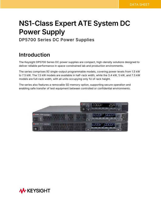
Every DP5700 Series power supply occupies 1U of rack height. The 1.5 kW models use a half-rack width enclosure, while the 3.4 kW, 5 kW, and 7.5 kW models use full-rack width enclosures. Front and rear air vents allow equipment to be stacked above or below the supply without blocking its airflow path.
The compact form factor supports test systems where rack space is limited. Optional rack-mount slide kits provide installation hardware for the different enclosure sizes. The data sheet includes dimension drawings to help engineers assess mechanical fit, wiring access, and the space needed for a selected power supply.
Selecting Output Voltage Current and Power
The DP5700 Series offers model-specific voltage and current ratings across its four power groups. Available models extend from low-voltage, high-current outputs to high-voltage outputs rated up to 1,500 V. The 5 kW group includes a 10 V, 500 A model, illustrating the range of configurations available for different loads.
Selection begins with the electrical needs of the device under test:
• Required output voltage and current range.
• Power needed during the planned test sequence.
• Programming and measurement accuracy.
• Ripple, noise, and transient response requirements.
• Applicable operating conditions and derating limits.
The specification tables provide model-level information for comparing these requirements. Engineers should review the relevant footnotes and setup conditions when assessing a particular operating point. The tables distinguish electrical ratings from supplemental characteristics, including resolution and temperature stability.
Parallel and Series Power Supply Configurations
For applications that require additional output current, supported 3.4 kW, 5 kW, and 7.5 kW models can operate in parallel, with up to 12 identical units. Parallel connections require units with matching voltage and current ratings and use the DP5706A Auto Parallel Cable. Parallel operation is not supported on the 1.5 kW half-rack models.
Two units can be connected in series to extend output voltage capability. Engineers must observe the output terminal isolation limits, grounding requirements, and rated operating conditions. The data sheet identifies the applicable limits for different output voltage groups, helping system designers plan configurations around the selected models and load connections.
AC Input Options and Model Identification
AC input requirements vary by power group and model suffix. The 1.5 kW models support single-phase 100–240 VAC input. The 3.4 kW models offer single-phase or three-phase configurations, while the 5 kW and 7.5 kW groups use three-phase input configurations.
For models with selectable AC input variants, the suffix identifies the supported range:
• S denotes the standard input range.
• L denotes the lower input range.
• H denotes the higher input range.
Not every suffix is available for every model. The AC input and output rating tables show the relevant combinations. Reviewing these tables helps align the power supply with the facility’s electrical infrastructure before installation.
Front Panel Control and Device Protection
Rotary knobs and buttons provide coarse and fine adjustment of voltage, current, protection settings, and power-on states. The front panel displays voltage and current simultaneously, while LED indicators show operating status and modes. A control lock helps prevent accidental changes to configured settings.
Protection functions include overtemperature, overcurrent, and overvoltage protection, which shut down the output when a corresponding fault occurs. Undervoltage protection prevents voltage adjustment below a defined limit. Together, the undervoltage and overvoltage settings establish a protection window for the connected load. These functions support test setup around the operating limits of the device under evaluation.
Programmable Functions for Power Testing
The DP5700 Series includes programmable internal resistance to emulate a voltage source with series resistance. This allows engineers to explore device behavior under defined source impedance conditions, including scenarios associated with batteries and other power sources.
The built-in arbitrary generator supports customized voltage or current waveforms for simulating power fluctuations and transient events. Synchronization with other instruments supports coordinated testing. Adjustable slew rate control lets engineers define how quickly output voltage changes during a test.
Analog programming offers another control method, using selectable voltage or resistance ranges. Voltage and current monitoring signals support observation of supply operation. These functions provide ways to configure repeatable electrical conditions for device characterization.
Interfaces Drivers and Test System Integration
Standard LAN, USB 2.0, and GPIB interfaces give engineers several options for connecting the DP5700 Series to automated test systems. The supplies support Standard Commands for Programmable Instruments, or SCPI, and include IVI.NET drivers to support software development.
Keysight IO Libraries Suite helps establish communication between a computer and connected instruments. The data sheet also documents interface capabilities, command response time, and saved instrument states. These details help engineers plan control sequences and connect power supply operation with the wider test workflow. Interface selection can follow the requirements of an existing system or the architecture of a new installation.
Removable Memory Accessories and Installation Planning
An optional removable SD memory feature supports equipment sanitization and data handling procedures in controlled environments. Teams should apply their own security processes when moving equipment between locations or preparing instruments for reuse.
Installation planning also includes rack-mount hardware, AC wiring, and environmental requirements. DP5700 power supplies are supplied without line cords or terminations, so users must provide suitable connections for their location and installation. The data sheet lists accessories, dimensions, environmental conditions, and service information to support these decisions. For engineers evaluating programmable DC power supplies, it brings the selection, configuration, and integration details together in one reference.