How to Debug LIN Bus Signals with an Oscilloscope

Monitor and Decode LIN Bus Communication
LIN is a single-ended signal-to-ground automotive serial bus commonly used to connect sensors, switches, actuators, and other body electronics to electronic control units (ECUs). Because these devices often communicate over relatively simple point-to-point networks, engineers need to verify both the integrity of the physical-layer signal and the accuracy of the transmitted messages during normal operation. Debugging LIN bus communication requires capturing the analog waveform while decoding protocol activity so that message timing, signal transitions, and communication behavior can be evaluated together. This makes it possible to investigate communication problems without separating protocol analysis from physical-layer measurements.
Performing the test requires an oscilloscope connected to the LIN signal using a standard high-impedance passive probe referenced to ground. Engineers configure the oscilloscope to trigger on selected LIN events, decode the captured traffic into readable protocol information, and display the decoded messages alongside the corresponding analog waveform. The time-correlated display allows engineers to compare message timing, observe the electrical characteristics associated with individual frames, and investigate whether unexpected communication behavior is related to the underlying physical-layer signal. Viewing protocol activity and waveform behavior together helps simplify LIN bus debugging while providing a clearer understanding of how communication events relate to the electrical performance of the network.

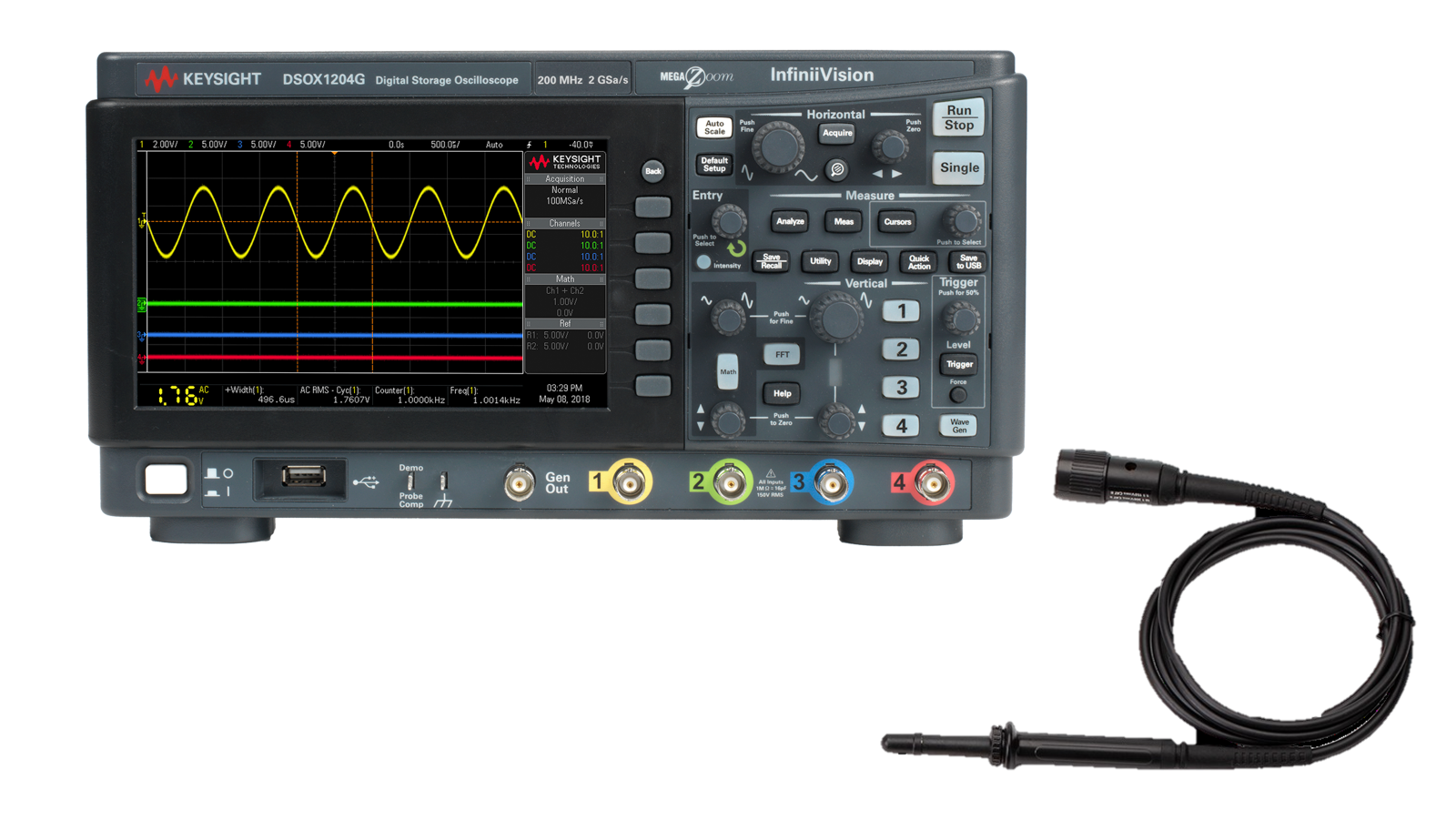
LIN Bus Debug Solution
See Demo of Automotive Serial Bus Debugging
Explore Products in Our LIN Bus Debug Solution
-

![]()
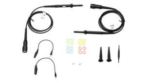
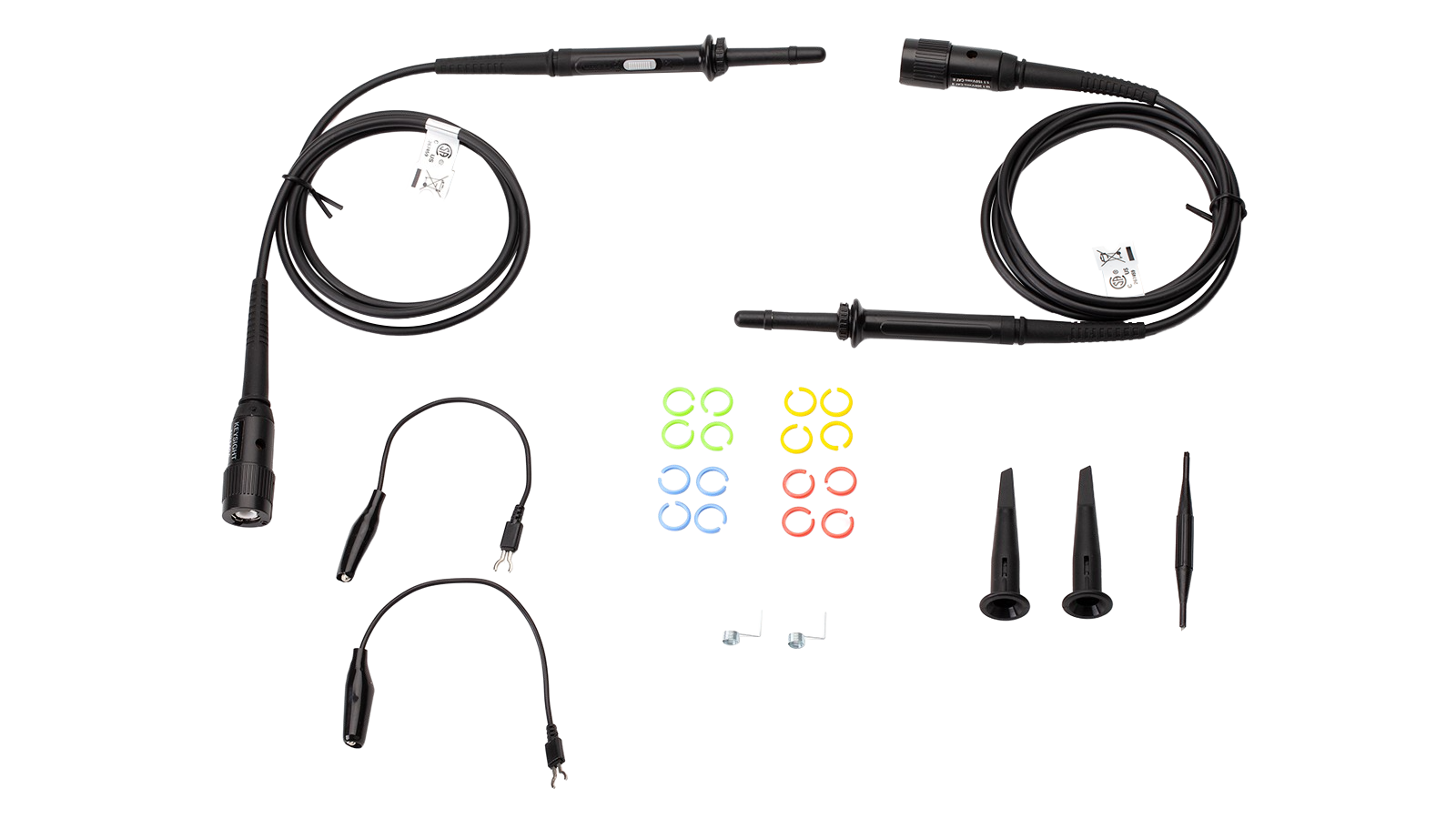
N2140A Passive Probe, 10:1, 200 MHz, 2-Pack
-
![]()
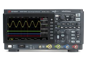
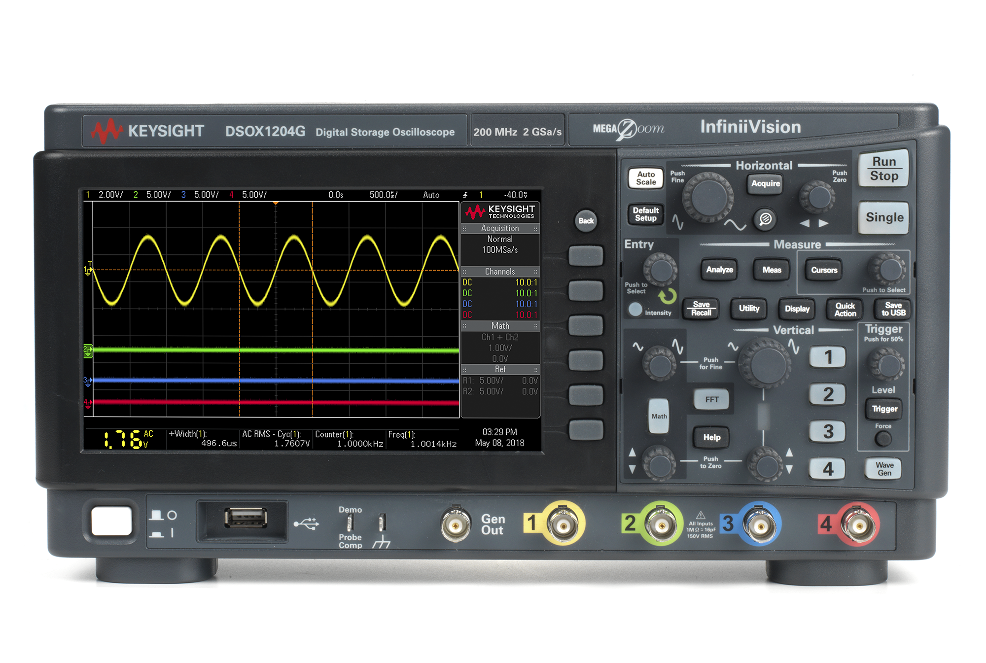
DSOX1204G Oscilloscope: 70/100/200 MHz, 4 Analog Channels, with a Built-in Waveform Generator

Discover Resources and Insights
Additional Resources for LIN Bus Debugging
Related Use Cases

-
![]()
Learn More
How to Find Intermittent Errors on Automotive Serial Buses
Find intermittent automotive serial bus errors using an Essential benchtop oscilloscope with hardware-based decoding and segmented memory.
Learn More

-
![]()
Learn More
How to Isolate CAN Bus Arbitration
Isolate CAN bus arbitration using an Essential Benchtop Oscilloscope with zone triggering, CAN message qualification, and segmented memory.
Learn More
-
![]()
Learn More
How to Trace Data Across Automotive Serial Bus Gateways
Trace data across automotive serial bus gateways using an Essential benchtop oscilloscope with dual-bus decoding and a time-interleaved protocol lister.
Learn More

Get in Touch with One of Our Experts
Need help finding the right solution for you?