How to Verify Average RF Power Across Different Signal Levels

Verify Average Power Across Signal Levels
Radio frequency (RF) devices often operate at multiple output levels as operating conditions, gain settings, or test parameters change. Engineers need to verify average power at each condition while maintaining a consistent measurement method across the test sequence. Differences in signal level can make measurement stability and sensor linearity important, particularly when comparing results across a broad range of device operating states. A sensor designed for average power measurements enables engineers to characterize these changes without requiring time-domain analysis of individual signal peaks.
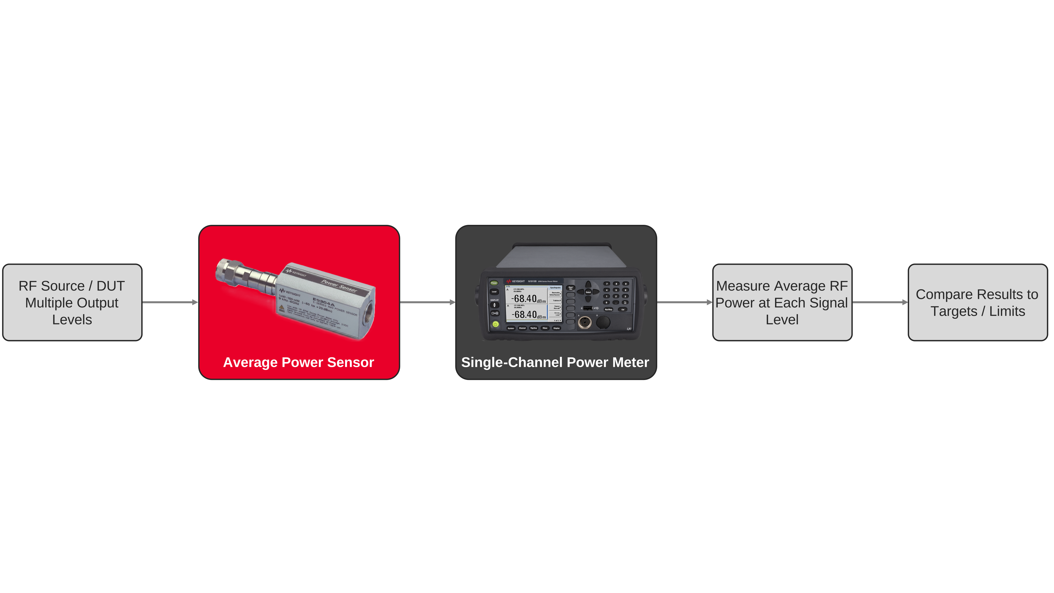
The measurement setup includes an average power sensor connected to a compatible power meter and the RF source or device under test. Engineers establish the measurement frequency, perform zeroing and calibration as required, and acquire average power at each defined operating condition. Measurements can then be compared with expected output levels, design targets, or test limits to evaluate how power changes as the device moves between operating states. Using the same sensor and measurement configuration across the sequence provides a consistent basis for comparing average RF power during component characterization, functional verification, and production testing.

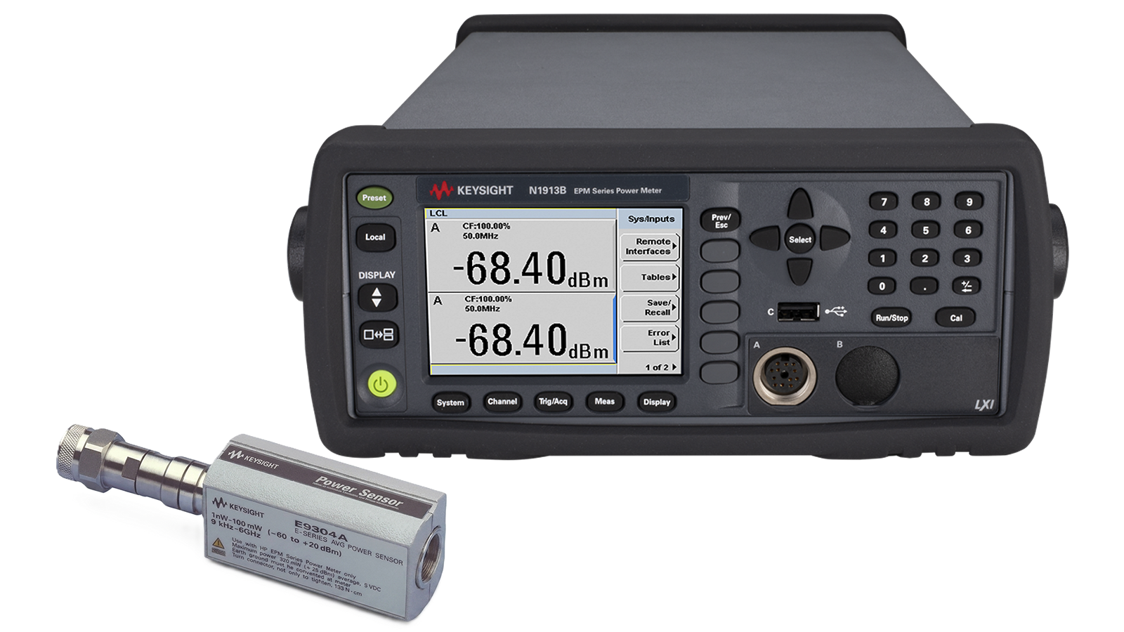
Average RF Power Verification Solution
See Block Diagram of Average RF Power Verification Solution

Explore Products in Our Average RF Power Verification Solution
-

![]()
E9300A E-Series Average Power Sensor
-
![]()
N1913B EPM Series Single-Channel Power Meter


Discover Resources and Insights
Additional Resources for Average RF Power Verification
Related Use Cases

-
![]()
Learn More
How to Perform Burst Power Measurement
Measure burst RF signal power using time-gated averaging with power meters, sensors, and automated control software for TDMA systems.
Learn More

-
![]()
Learn More
How to Measure RF Power During Rapid Amplitude Switching
Measure RF power during rapid amplitude transitions using a power meter, fast-response sensors, continuous acquisition, and automated measurement techniques.
Learn More
-
![]()
Learn More
How to Measure Average Power of Frequency-Hopping Signals
Measure average RF power of frequency-hopping signals using power meters, sensors, and time-aligned measurement techniques for accurate results.
Learn More

Get in Touch with One of Our Experts
Need help finding the right solution for you?