Learn More
keysight:dtx/solutions/facets/development-area/power,keysight:dtx/solutions/facets/industry/automotive,segmentation:campaign/Automotive_Energy,segmentation:product-category/Automotive_Testing,segmentation:product-category/Automotive_Testing/Automotive_Power,segmentation:business-unit/EISG,keysight:product-lines/ae,segmentation:funnel/bofu,keysight:dtx/solutions/facets/workflow-stage/qa,keysight:dtx/solutions/facets/design-and-test-product/power-analyzer,keysight:dtx/solutions/facets/industry/grid-and-energy,keysight:models/sl/sl1840a,keysight:models/sl/sl1047a,keysight:models/sl/sl1093akeysight:dtx/solutions/facets/development-area/power,keysight:dtx/solutions/facets/industry/automotive,segmentation:campaign/Automotive_Energy,segmentation:product-category/Automotive_Testing,segmentation:product-category/Automotive_Testing/Automotive_Power,segmentation:business-unit/EISG,keysight:product-lines/ae,segmentation:funnel/bofu,keysight:dtx/solutions/facets/workflow-stage/qa,keysight:dtx/solutions/facets/design-and-test-product/power-analyzer,keysight:dtx/solutions/facets/industry/grid-and-energy,keysight:models/sl/sl1840a,keysight:models/sl/sl1047a,keysight:models/sl/sl1093akeysight:dtx/solutions/facets/development-area/power,keysight:dtx/solutions/facets/industry/automotive,segmentation:campaign/Automotive_Energy,segmentation:product-category/Automotive_Testing,segmentation:product-category/Automotive_Testing/Automotive_Power,segmentation:business-unit/EISG,keysight:product-lines/ae,segmentation:funnel/bofu,keysight:dtx/solutions/facets/workflow-stage/qa,keysight:dtx/solutions/facets/design-and-test-product/power-analyzer,keysight:dtx/solutions/facets/industry/grid-and-energy,keysight:models/sl/sl1840a,keysight:models/sl/sl1047a,keysight:models/sl/sl1093akeysight:dtx/solutions/facets/development-area/power,keysight:dtx/solutions/facets/industry/automotive,segmentation:campaign/Automotive_Energy,segmentation:product-category/Automotive_Testing,segmentation:product-category/Automotive_Testing/Automotive_Power,segmentation:business-unit/EISG,keysight:product-lines/ae,segmentation:funnel/bofu,keysight:dtx/solutions/facets/workflow-stage/qa,keysight:dtx/solutions/facets/design-and-test-product/power-analyzer,keysight:dtx/solutions/facets/industry/grid-and-energy,keysight:models/sl/sl1840a,keysight:models/sl/sl1047a,keysight:models/sl/sl1093akeysight:dtx/solutions/facets/development-area/power,keysight:dtx/solutions/facets/industry/automotive,segmentation:campaign/Automotive_Energy,segmentation:product-category/Automotive_Testing,segmentation:product-category/Automotive_Testing/Automotive_Power,segmentation:business-unit/EISG,keysight:product-lines/ae,segmentation:funnel/bofu,keysight:dtx/solutions/facets/workflow-stage/qa,keysight:dtx/solutions/facets/design-and-test-product/power-analyzer,keysight:dtx/solutions/facets/industry/grid-and-energy,keysight:models/sl/sl1840a,keysight:models/sl/sl1047a,keysight:models/sl/sl1093akeysight:dtx/solutions/facets/development-area/power,keysight:dtx/solutions/facets/industry/automotive,segmentation:campaign/Automotive_Energy,segmentation:product-category/Automotive_Testing,segmentation:product-category/Automotive_Testing/Automotive_Power,segmentation:business-unit/EISG,keysight:product-lines/ae,segmentation:funnel/bofu,keysight:dtx/solutions/facets/workflow-stage/qa,keysight:dtx/solutions/facets/design-and-test-product/power-analyzer,keysight:dtx/solutions/facets/industry/grid-and-energy,keysight:models/sl/sl1840a,keysight:models/sl/sl1047a,keysight:models/sl/sl1093akeysight:dtx/solutions/facets/development-area/power,keysight:dtx/solutions/facets/industry/automotive,segmentation:campaign/Automotive_Energy,segmentation:product-category/Automotive_Testing,segmentation:product-category/Automotive_Testing/Automotive_Power,segmentation:business-unit/EISG,keysight:product-lines/ae,segmentation:funnel/bofu,keysight:dtx/solutions/facets/workflow-stage/qa,keysight:dtx/solutions/facets/design-and-test-product/power-analyzer,keysight:dtx/solutions/facets/industry/grid-and-energy,keysight:models/sl/sl1840a,keysight:models/sl/sl1047a,keysight:models/sl/sl1093akeysight:dtx/solutions/facets/development-area/power,keysight:dtx/solutions/facets/industry/automotive,segmentation:campaign/Automotive_Energy,segmentation:product-category/Automotive_Testing,segmentation:product-category/Automotive_Testing/Automotive_Power,segmentation:business-unit/EISG,keysight:product-lines/ae,segmentation:funnel/bofu,keysight:dtx/solutions/facets/workflow-stage/qa,keysight:dtx/solutions/facets/design-and-test-product/power-analyzer,keysight:dtx/solutions/facets/industry/grid-and-energy,keysight:models/sl/sl1840a,keysight:models/sl/sl1047a,keysight:models/sl/sl1093akeysight:dtx/solutions/facets/development-area/power,keysight:dtx/solutions/facets/industry/automotive,segmentation:campaign/Automotive_Energy,segmentation:product-category/Automotive_Testing,segmentation:product-category/Automotive_Testing/Automotive_Power,segmentation:business-unit/EISG,keysight:product-lines/ae,segmentation:funnel/bofu,keysight:dtx/solutions/facets/workflow-stage/qa,keysight:dtx/solutions/facets/design-and-test-product/power-analyzer,keysight:dtx/solutions/facets/industry/grid-and-energy,keysight:models/sl/sl1840a,keysight:models/sl/sl1047a,keysight:models/sl/sl1093akeysight:dtx/solutions/facets/development-area/power,keysight:dtx/solutions/facets/industry/automotive,segmentation:campaign/Automotive_Energy,segmentation:product-category/Automotive_Testing,segmentation:product-category/Automotive_Testing/Automotive_Power,segmentation:business-unit/EISG,keysight:product-lines/ae,segmentation:funnel/bofu,keysight:dtx/solutions/facets/workflow-stage/qa,keysight:dtx/solutions/facets/design-and-test-product/power-analyzer,keysight:dtx/solutions/facets/industry/grid-and-energy,keysight:models/sl/sl1840a,keysight:models/sl/sl1047a,keysight:models/sl/sl1093akeysight:dtx/solutions/facets/development-area/power,keysight:dtx/solutions/facets/industry/automotive,segmentation:campaign/Automotive_Energy,segmentation:product-category/Automotive_Testing,segmentation:product-category/Automotive_Testing/Automotive_Power,segmentation:business-unit/EISG,keysight:product-lines/ae,segmentation:funnel/bofu,keysight:dtx/solutions/facets/workflow-stage/qa,keysight:dtx/solutions/facets/design-and-test-product/power-analyzer,keysight:dtx/solutions/facets/industry/grid-and-energy,keysight:models/sl/sl1840a,keysight:models/sl/sl1047a,keysight:models/sl/sl1093akeysight:dtx/solutions/facets/development-area/power,keysight:dtx/solutions/facets/industry/automotive,segmentation:campaign/Automotive_Energy,segmentation:product-category/Automotive_Testing,segmentation:product-category/Automotive_Testing/Automotive_Power,segmentation:business-unit/EISG,keysight:product-lines/ae,segmentation:funnel/bofu,keysight:dtx/solutions/facets/workflow-stage/qa,keysight:dtx/solutions/facets/design-and-test-product/power-analyzer,keysight:dtx/solutions/facets/industry/grid-and-energy,keysight:models/sl/sl1840a,keysight:models/sl/sl1047a,keysight:models/sl/sl1093akeysight:dtx/solutions/facets/development-area/power,keysight:dtx/solutions/facets/industry/automotive,segmentation:campaign/Automotive_Energy,segmentation:product-category/Automotive_Testing,segmentation:product-category/Automotive_Testing/Automotive_Power,segmentation:business-unit/EISG,keysight:product-lines/ae,segmentation:funnel/bofu,keysight:dtx/solutions/facets/workflow-stage/qa,keysight:dtx/solutions/facets/design-and-test-product/power-analyzer,keysight:dtx/solutions/facets/industry/grid-and-energy,keysight:models/sl/sl1840a,keysight:models/sl/sl1047a,keysight:models/sl/sl1093akeysight:dtx/solutions/facets/development-area/power,keysight:dtx/solutions/facets/industry/automotive,segmentation:campaign/Automotive_Energy,segmentation:product-category/Automotive_Testing,segmentation:product-category/Automotive_Testing/Automotive_Power,segmentation:business-unit/EISG,keysight:product-lines/ae,segmentation:funnel/bofu,keysight:dtx/solutions/facets/workflow-stage/qa,keysight:dtx/solutions/facets/design-and-test-product/power-analyzer,keysight:dtx/solutions/facets/industry/grid-and-energy,keysight:models/sl/sl1840a,keysight:models/sl/sl1047a,keysight:models/sl/sl1093a
How to Test EV Fast-Chargers
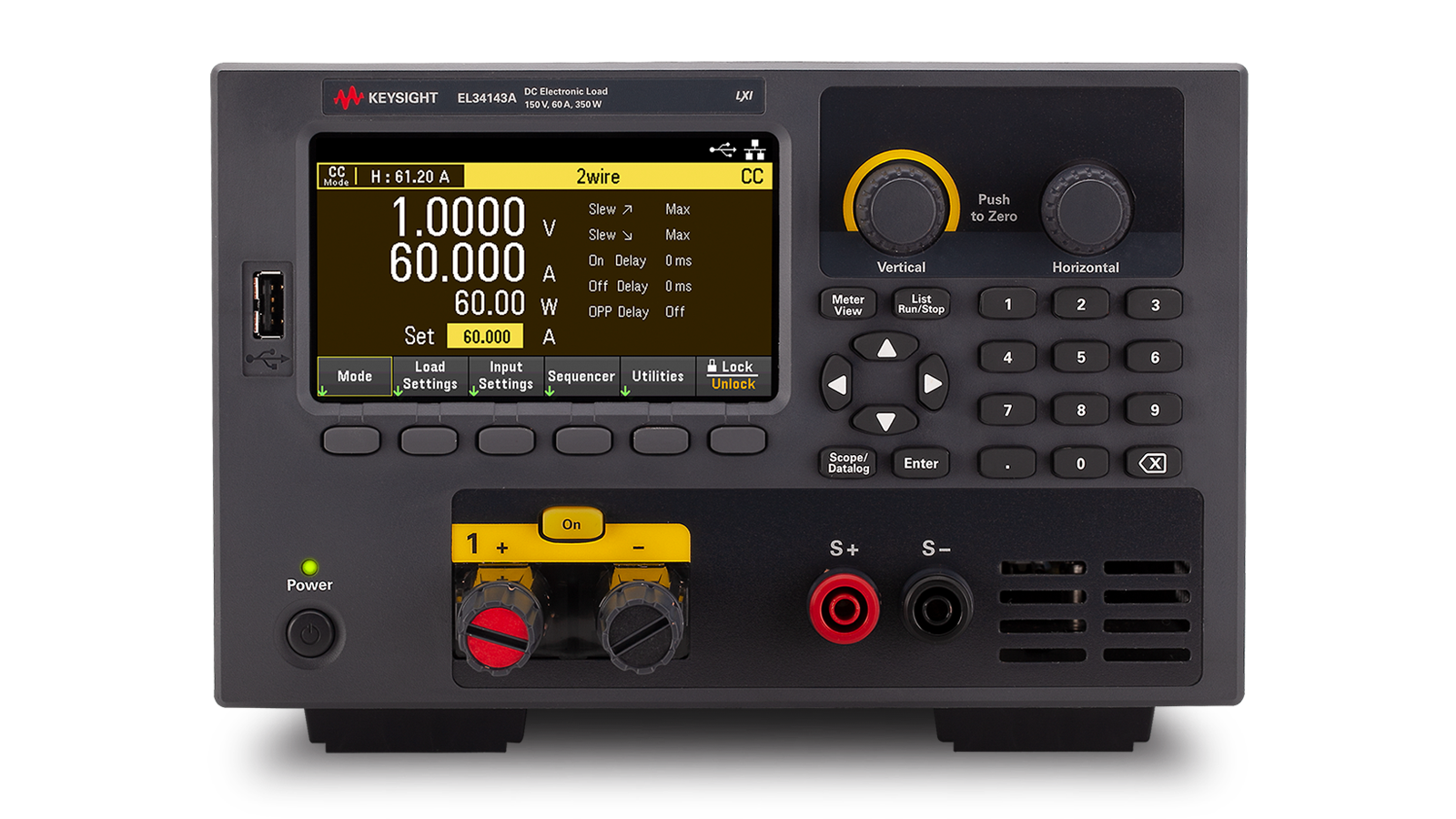
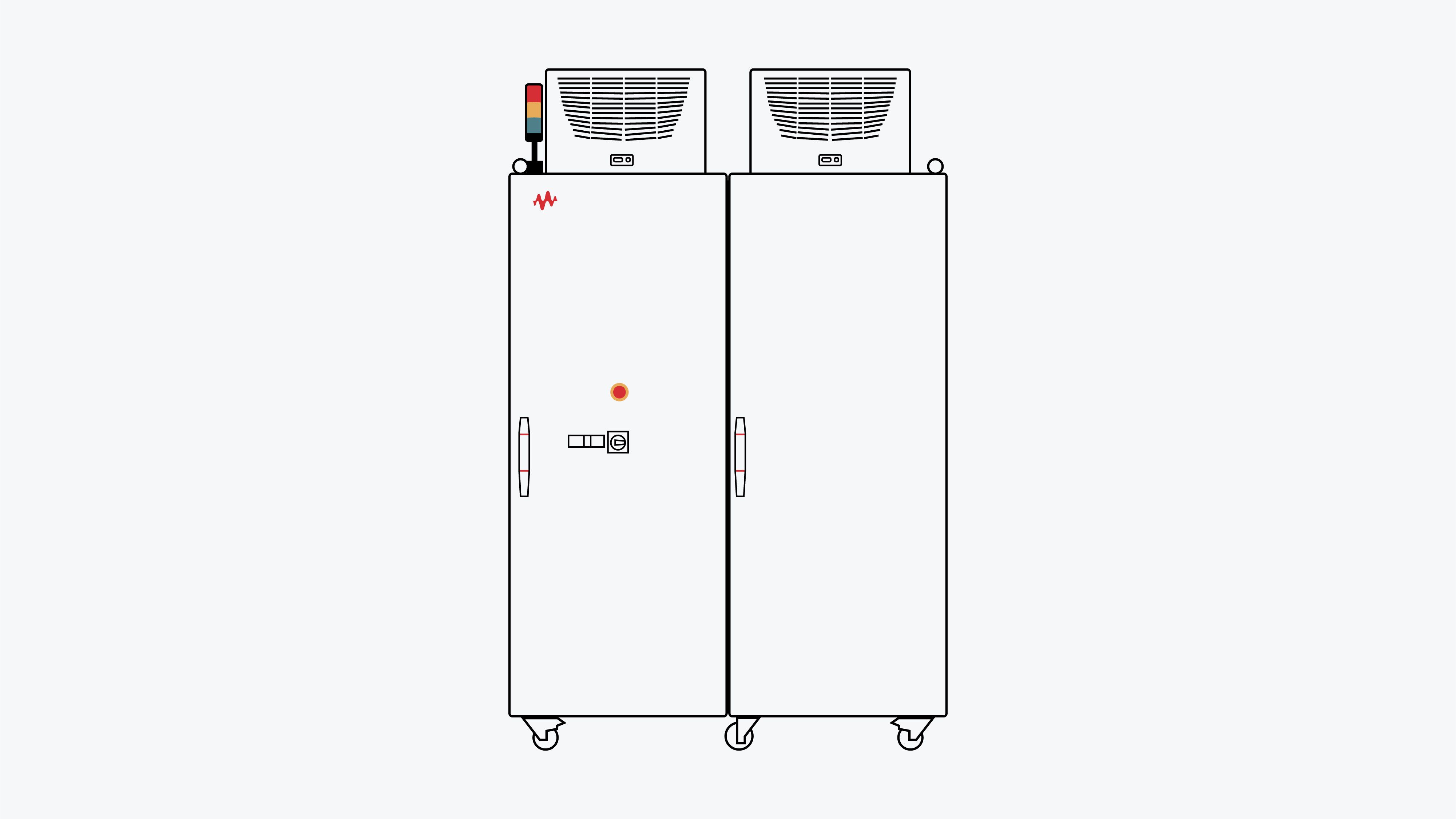
Testing DC fast-charging (DCFC) parameters requires sinking very high power loads coming from the EV charger, and emulating vehicle communications. Learn how to emulate an EV battery to test the interoperability of different EVs and DC fast charging stations.
Learn More