How to Improve Passive Component Measurement Accuracy

Control Conditions for Repeatable Impedance Measurements
Passive component measurement accuracy depends on controlling the electrical conditions under which resistance, capacitance, inductance, and impedance are measured. The test requires an inductance, capacitance, and resistance (LCR) meter, an appropriate fixture or lead set, a defined test frequency, and a repeatable connection to the device under test. Begin by selecting a test frequency that represents the component behavior being evaluated, because capacitive and inductive reactance change with frequency and can alter both the primary measurement value and associated secondary parameters. Test frequency selection should therefore remain consistent when comparing components, verifying nominal values, or repeating measurements over time. The selected measurement parameter should also correspond to the electrical characteristic being evaluated. Resistance, capacitance, and inductance can be represented using series or parallel equivalent circuits depending on the component impedance and operating conditions. Selecting an appropriate equivalent-circuit representation helps ensure that the displayed value corresponds to the electrical behavior being evaluated. An LCR meter may also provide parameters such as impedance magnitude, phase angle, dissipation factor, quality factor, or equivalent series resistance, which can be evaluated together with the primary component value. Establishing these measurement conditions before collecting data provides a controlled basis for passive component measurement and makes differences between measurements easier to interpret. When measurements are compared across several frequencies, engineers can determine whether changes originate from the expected frequency response of the component rather than from inconsistent test settings. This approach supports impedance measurement accuracy by treating frequency, measurement parameter, equivalent circuit, and connection method as defined parts of the test rather than incidental instrument settings.
The physical measurement interface must also be controlled because fixtures, adapters, test leads, contacts, and surrounding conductors can contribute unwanted resistance, capacitance, and inductance to the result. Test fixture compensation is used to reduce these residual electrical effects before the component is measured. Open compensation can characterize stray admittance associated with the fixture when no device is connected, while short compensation can characterize residual series impedance when the measurement terminals are connected together. The applicable compensation procedure should be performed using the same fixture, leads, connection geometry, and measurement conditions that will be used for the device under test. After compensation, the fixture geometry should remain unchanged so that the correction continues to represent the measurement interface. Lead length, contact pressure, component placement, and terminal cleanliness should also remain consistent between measurements. These practices become increasingly important when the value being measured approaches the magnitude of the fixture’s own residual electrical characteristics. Small capacitances can be influenced by stray capacitance between conductors, low inductances can be affected by lead inductance, and low resistance measurements can be influenced by contact and conductor resistance. Engineers can assess measurement repeatability by disconnecting and reconnecting the component, repeating the reading under the same settings, and observing whether the measured result remains within an acceptable range. When test fixture compensation, test frequency selection, and connection conditions are controlled together, the resulting LCR meter measurements provide a more consistent representation of component behavior. This structured workflow improves impedance measurement accuracy and provides repeatable resistance, capacitance, inductance, and impedance data for passive component measurement across characterization, troubleshooting, inspection, and bench verification activities.


Passive Component Measurement Accuracy Solution
Block Diagram of Passive Component Measurement Accuracy Solution


Explore Products in Our Passive Component Measurement Accuracy Solution
-

![]()
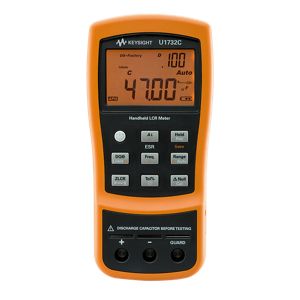
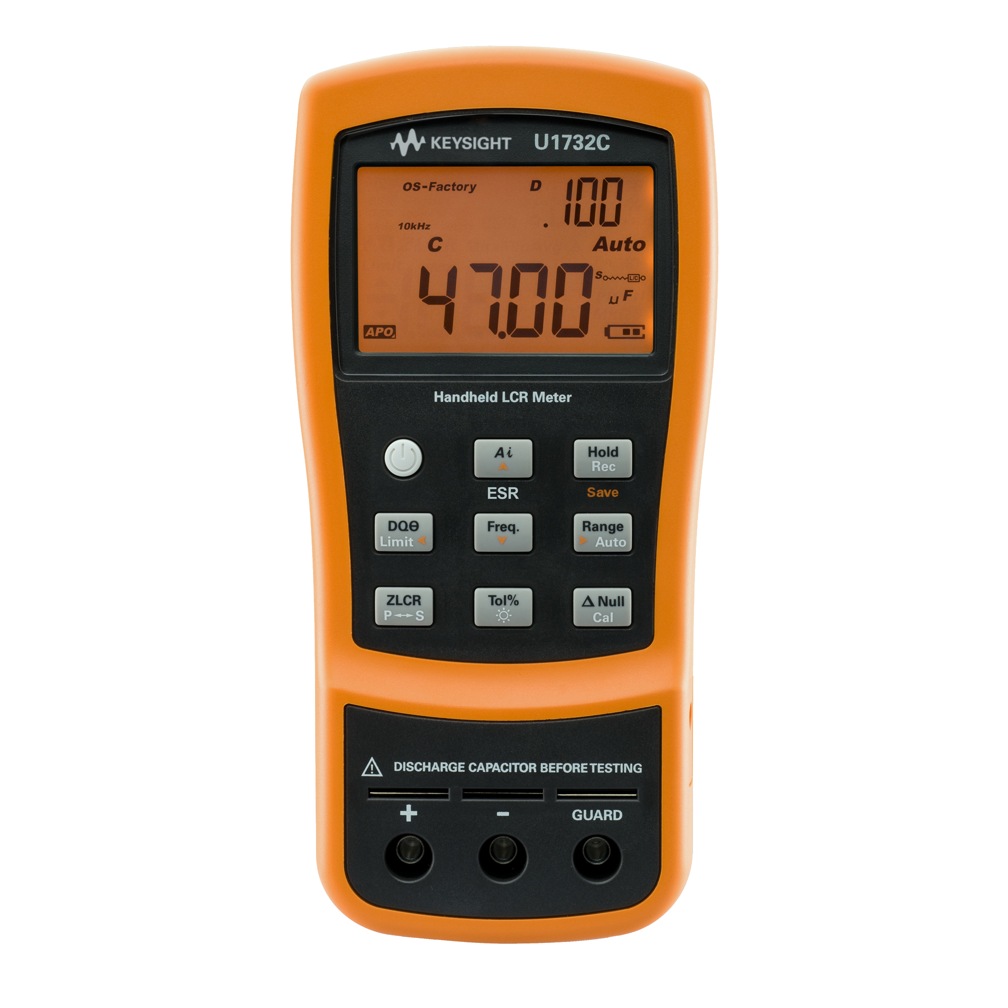
U1732C 100Hz / 120Hz / 1kHz / 10kHz Handheld LCR Meter

Discover Resources and Insights
Additional Resources for Passive Component Measurement Accuracy
Related Use Cases

-
![]()
Learn More
How to Measure Passive Component Impedance
Measure resistance, inductance, capacitance, and impedance characteristics of passive components using a handheld LCR meter. This workflow covers selecting an appropriate test frequency, connecting the device under test, choosing series or parallel measurement behavior, and interpreting primary and secondary component parameters.
Learn More

-
![]()
Learn More
How to Verify Capacitive Sensor Element Consistency
Verify capacitive sensor element consistency using precision capacitance measurements to ensure uniform performance across devices.
Learn More
-
![]()
Learn More
How to Characterize Ceramic Capacitor DC Bias Derating
Characterize ceramic capacitor DC bias derating using precision capacitance measurements to ensure accurate circuit design and performance with a capacitance meter.
Learn More

Get in Touch with One of Our Experts
Need help finding the right solution for you?