Choose a country or area to see content specific to your location

    Enable browser cookies for improved site capabilities and performance.
    Keysight Technologies
    Toggle Menu
    Chat Live
    Contact Us
    Welcome

    Welcome

    • My Profile
    • Logout
    • Login
    • Register
    Quote
    United States

    Confirm Your Country or Area

    United States

    • 中国
    • 日本
    • 繁體中文
    • 한국
    • Россия
    • Brasil
    • Canada
    • Deutschland
    • France
    • India
    • Malaysia
    • United Kingdom
    • United States
    • Australia
    • Austria
    • Belgium
    • Denmark
    • Finland
    • Hong Kong, China
    • Ireland
    • Israel
    • Italy
    • Mexico
    • Netherlands
    • Singapore
    • Spain
    • Sweden
    • Switzerland (German)
    • Thailand
    • more...

    Please Confirm

    Confirm your country to access relevant pricing, special offers, events, and contact information.

    • Products + Services
      • Oscilloscopes + Analyzers
        • Oscilloscopes
        • Spectrum Analyzers (Signal Analyzers)
        • Network Analyzers
        • Logic Analyzers
        • Protocol Analyzers and Exercisers
        • Bit Error Ratio Testers
        • Noise Figure Analyzers and Noise Sources
        • High-Speed Digitizers and Multichannel DAQ Solutions
        • AC Power Analyzers
        • DC Power Analyzers
        • Materials Test Equipment
        • Device Current Waveform Analyzers
        • Parameter and Device Analyzers, Curve Tracers
      • Meters
        • Digital Multimeters
        • Phase Noise Measurement
        • Power Meters and Power Sensors
        • 53200 Series RF and Universal Frequency Counter / Timers
        • LCR Meters and Impedance Measurement Products
        • B2980 Series Femto / Picoammeter and Electrometer Meters
      • Generators, Sources + Power
        • Signal Generators (Signal Sources)
        • Waveform and Function Generators
        • Arbitrary Waveform Generators
        • Pulse Generator Products
        • HEV/EV/Grid Emulators and Test Systems
        • DC Power Supplies
        • Source Measure Units
        • DC Electronic Load
        • AC Power Sources
      • Software
        • Application Software
        • Application Software Testing
        • PathWave Design Software
        • PathWave Test Software
        • Productivity Software
        • Software Enterprise Agreement
        • All Design + Test Software  
      • Wireless
        • Wireless Network Emulators
        • Channel Emulators
        • Nemo Wireless Network Solutions
        • 5G OTA Chambers
        • Wireless Analyzers
        • IoT Regulatory Compliance Solutions
      • Modular Instruments
        • PXI Products
        • AXIe Products
        • Data Acquisition – DAQ
        • USB Products
        • VXI Products
        • Reference Solutions
        • All Modular Instruments  
      • Network Test
        • Protocol and Load Test
        • Network Test Hardware
        • Cloud Test
        • Performance Monitoring
        • 5G NR Base Station Test
        • Radio Access and Core Network Test
        • Keysight Cyber Training Simulator
        • Network Modeling
        • All Network Test  
      • Network Security + Visibility
        • Network Packet Brokers
        • Cloud Visibility
        • Network Taps
        • Bypass Switches
        • Network Security
        • Application and Threat Intelligence
      • Additional Products
        • In-circuit Test Systems
        • Application-Specific Test Systems And Components
        • Parametric Test Solutions
        • Photonic Test & Measurement Products
        • Laser Interferometers and Calibration Systems
        • Monolithic Laser Combiners & Precision Optics
        • MMIC Millimeter-Wave and Microwave Devices
      • Services
        • KeysightCare Service and Support
        • KeysightAccess Service
        • Calibration Services
        • Repair Services
        • Technology Refresh Services
        • Test as a Service (TaaS)
        • Network/Security Services
        • Consulting Services
        • Financial Services
        • Education Services
        • Keysight Support Portal
        • Used Equipment
        • All Services  
      • All Products, Software, Services  
    • Solutions
      • 5G
      • Cloud
      • Connected Car
      • Data Center Infrastructure
      • Design + Automation
      • Emerging Technologies
      • Energy Ecosystem
      • High-Speed Digital System Design
      • Internet of Things
      • Manufacturing Test
      • Measurement Fundamentals
      • Network Security
      • Network Test
      • Network Visibility
      • SDN, NFV, Virtualization
      • Software Test Automation
      • All Solutions  
    • Industries
      • Aerospace + Defense
      • Automotive + Energy
      • Communications
      • Education
      • Enterprise
      • Government
      • Semiconductor
      • Service Providers
      • All Industries + Technologies  
    • Insights
      • Discover Insights
      • Success Stories
      • Blog
      • Keysight University
    • Resources
    • Buy
    • Support
      • Keysight Product Support
      • Ixia Product Support
    No product matches found - System Exception
    Becoming Familiar with your Standard Oscilloscope Probe
    Application Notes

    Becoming Familiar with your Standard Oscilloscope Probe

    Show Description

    Introduction

    An often overlooked, important part of oscilloscope testing is the probe you use. The main role of a probe is to connect your target device under test (DUT) to the oscilloscope’s input so you can pick up the signal from the DUT and view the waveform on the oscilloscope screen.

    But keep in mind that an oscilloscope probe is not just a piece of wire with a pointy tip attached to it. There is more to it that you need to know if you want correct testing results. The majority of oscilloscopes with ≤1 GHz bandwidth come standard with one high-impedance passive probe per oscilloscope channel. This is the probe the majority of people will use.

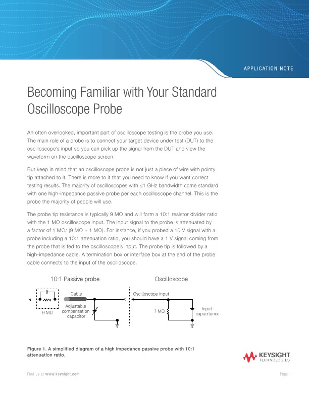
    The probe tip resistance is typically 9 MΩ and will form a 10:1 resistor divider ratio with the 1 MΩ oscilloscope input. The input signal to the probe is attenuated by a factor of 1 MΩ/ (9 MΩ + 1 MΩ). For instance, if you probed a 10 V signal with a probe including a 10:1 attenuation ratio, you should have a 1 V signal coming from the probe that is fed to the oscilloscope’s input. The probe tip is followed by a high-impedance cable. A termination box or interface box at the end of the probe cable connects to the input of the oscilloscope.

    The primary feature of this probe is its very high impedance. At DC, the probe’s input impedance has 10 MΩ of resistance, and as the frequency goes up, the input impedance of the probe falls off as the capacitive reactance of the probe gets larger. 

    The standard passive probe is the most rugged, flexible, and inexpensive probe that also gives a very wide input dynamic range - making this probe an excellent choice for general-purpose probing and troubleshooting.

    Probe Compensation

    Most standard passive probes have an adjustable compensation capacitor for matching RC coefficient to the input capacitance of the oscilloscope. The probe’s adjustable compensation capacitor can be adjusted to cancel the input capacitance of the oscilloscope. To compensate the probe, the oscilloscope probe is connected to the probe compensation terminal to make the square wave look as square and flat-topped as possible. Before making any oscilloscope measurements, you should connect your probes to the probe compensation signal on the front panel to ensure they are properly adjusted.

    Dual Attenuation Ratio Probe

    Most standard passive probes offer a 10:1 attenuation ratio. A standard passive probe usually provides a dual attenuation ratio - user-selectable 10:1 and 1:1 range. The 1:1/10:1 probe has a switch that inserts what’s usually a 9 MΩ resistor in series with the signal. In the oscilloscope, there’s a 1 MΩ resistor for forming 10:1 input attenuation ratio. In the 1:1 mode, there is no series resistor on the probe side and the total DC resistance seen from the probe tip is only 1 MΩ on the oscilloscope’s input.

    The primary benefit of using a dual-attenuation ratio probe is it provides the convenience of both 10:1 and 1:1 attenuation. In general, the 1:1 mode of the probe provides lower noise, making it ideal for measuring low-level signals such as ripple and noise of a power supply. However, the 1:1 mode will produce a significant amount of capacitance appearing in parallel with the oscilloscope’s input, resulting in the reduction of the bandwidth down to approximately 25 MHz.

    In the following example, a 10:1/1:1 probe is used to measure the power supply output noise with each attenuation ratio setting. At 1:1 mode, the measured noise is favorable with almost half the noise measured with the 10:1 mode.

    Change email?
    Required field

    Required field

    Required field

    Required field

    Required field

    Required field

    Required field

    Required field

    Required field

    Required field

    Required field

    Required field

    Required field

    Required field

    Required field

    By clicking the button, you are providing Keysight with your personal data. For information on how we use this data, see the Keysight Privacy Statement.

    Thank you!
    Download

    Explore

    • Products + Services
    • Solutions
    • Industries
    • Events
    • Keysight University

    Insights

    • Discover Insights
    • Success Stories
    • Resources
    • Blog
    • Community

    Partners

    Support

    • Keysight Product Support
    • Ixia Product Support
    • Manage Software Licenses
    • Product Order Status
    • Parts

    About Keysight

    • Newsroom
    • Investor Relations
    • Corporate Social Responsibility
    • Diversity, Equity, and Inclusion
    • Modern Slavery Act Transparency Statement
    • Careers

    • Facebook: Connect with Keysight LinkedIn: Connect with Keysight Twitter: Connect with Keysight YouTube: Connect with Keysight WeChat:Connect with Keysight
    • © Keysight Technologies 2000–2022
    • Privacy
    • Terms
    • Feedback