How to Improve Signal Integrity Validation for High-Speed Designs

Broadband Signal Integrity Validation
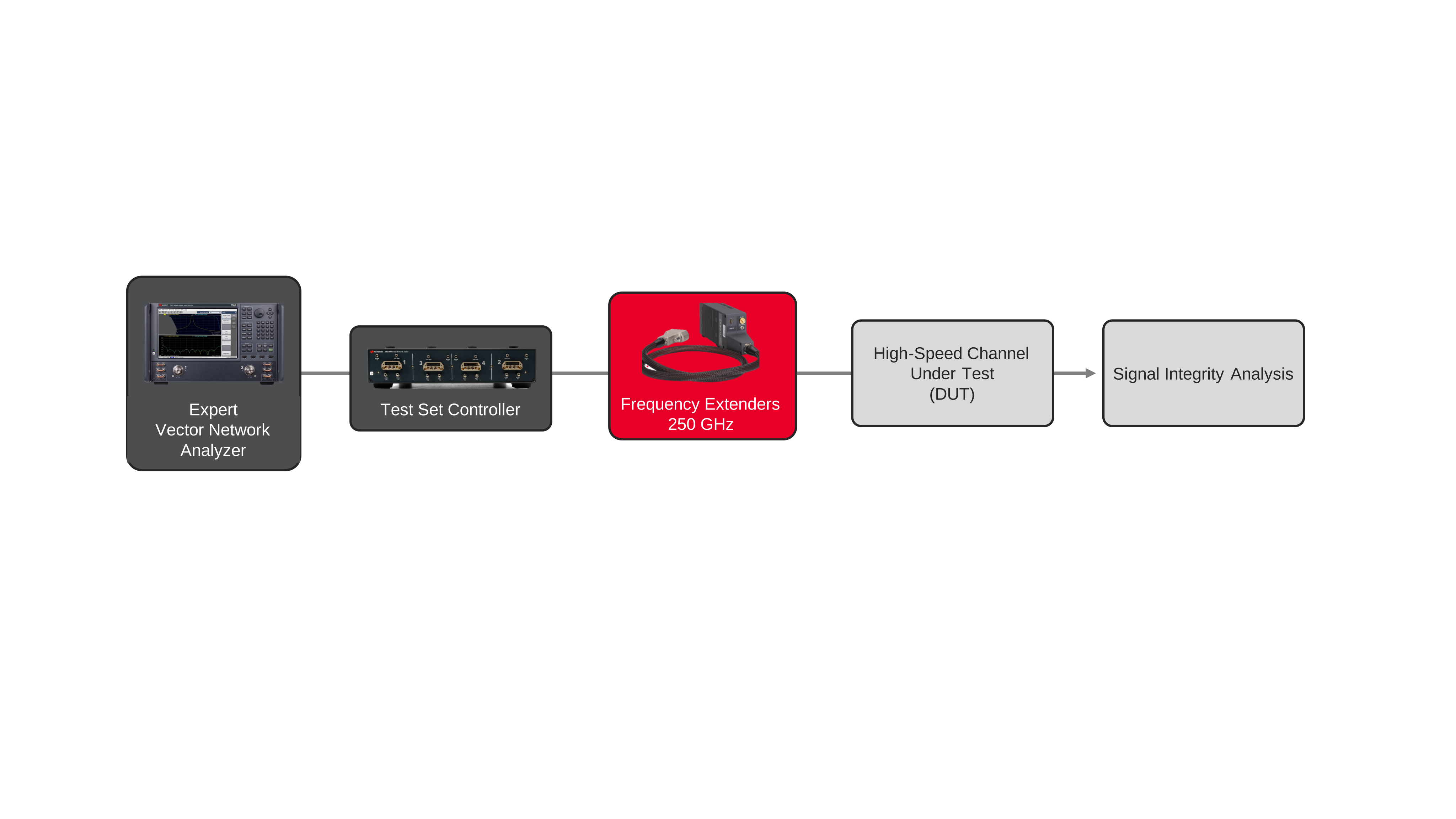
High-speed electronic channels often contain impedance discontinuities that are difficult to identify using conventional frequency-domain measurements alone. Signal integrity validation combines broadband network analysis with time domain reflectometry (TDR), fixture removal, and channel analysis to evaluate printed circuit boards, connectors, cable assemblies, packages, vias, and other passive structures that affect channel performance. The measurement configuration includes a vector network analyzer, broadband frequency extenders, a test set controller, calibration standards, and fixtures or probes for broadband scattering parameter measurements across a continuous frequency range extending to 250 GHz. The resulting data supports both frequency-domain and time-domain analysis.
Broadband scattering parameter measurements can be transformed into impedance profiles that reveal the physical location of discontinuities affecting signal transmission. Engineers use these results to isolate connector transitions, remove fixture effects through de-embedding, evaluate differential transmission paths, and compare measured channel behavior with simulation models. The workflow enables rapid identification of design issues before prototype release while improving confidence in signal integrity performance across increasingly demanding high-speed digital interfaces.

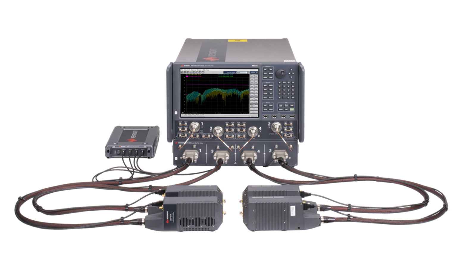
High-Speed Signal Integrity Solution
See Block Diagram of High-Speed Signal Integrity Solution

Explore Products in Our High-Speed Signal Integrity Solution
-

![]()
N5290A PNA Millimeter Wave System
-
![]()
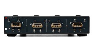
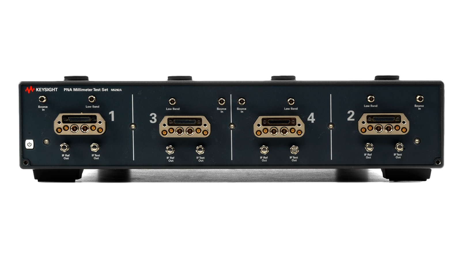
N5292A Millimeter-wave Test Set Controller for PNA/PNA-X Network Analyzer Series, 2- or 4-port
-
![]()
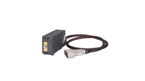
NA5307A Frequency Extender, 250 GHz



Discover Resources and Insights
Additional Resources for Signal Integrity Validation
Related Use Cases


-
![]()
Learn More
How to Validate AI Data Center Interconnects to 250 GHz
Validate AI data center interconnects to 250 GHz using a vector network analyzer and broadband frequency extenders.
Learn More

-
![]()
Learn More
How to Verify Differential Interconnect Impedance for High-Speed Designs
Verify differential interconnect impedance using a vector network analyzer, time-domain analysis software, and electronic calibration.
Learn More
-
![]()
Learn More
How to Validate Multi-Chassis Time Synchronization
Validate nanosecond-accurate time alignment across multiple network test chassis using Metronome and IxNetwork synchronization architectures.
Learn More

Get in Touch with One of Our Experts
Need help finding the right solution for you?