How to Characterize Synchronous Ethernet Clock Synchronization

Characterize SyncE Clock Quality
Synchronous Ethernet (SyncE) clock characterization uses an Ethernet test interface, a stable frequency reference, and a network element configured to recover or distribute physical-layer frequency. The test system supplies a defined reference and communicates clock-quality information over the Ethernet link. The engineer selects the interface rate, identifies the active clock source, and records Ethernet Synchronization Messaging Channel (ESMC) status and quality-level information. Where the network element exposes a clock output, a timing instrument can measure the recovered frequency directly; otherwise, a compatible Ethernet timing measurement interface is required. Establish the reference topology, measurement interval, and source-selection rules before collecting data. Record link status and the configuration of each reference and clock-recovery path alongside the SyncE clock synchronization results.
Begin the characterization with stable input conditions and acquire a baseline Ethernet clock wander trace. Record time interval error, available clock-quality metrics, and the observed frequency-lock state. Repeat the measurement after changing the announced quality level, switching the selected reference, or applying a defined impairment when the connected instruments support that function. Capture the resulting clock transition and recovery behavior without changing unrelated network settings. Compare the measured wander with the applicable International Telecommunication Union Telecommunication Standardization Sector (ITU-T) criteria or a documented engineering limit. Preserve the test duration, Ethernet interface speed, source-priority settings, and timing-reference state for each capture. This procedure links SyncE clock quality and ESMC quality level observations to the measured behavior of the recovered Ethernet clock.
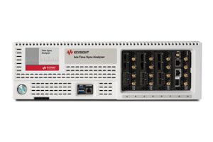
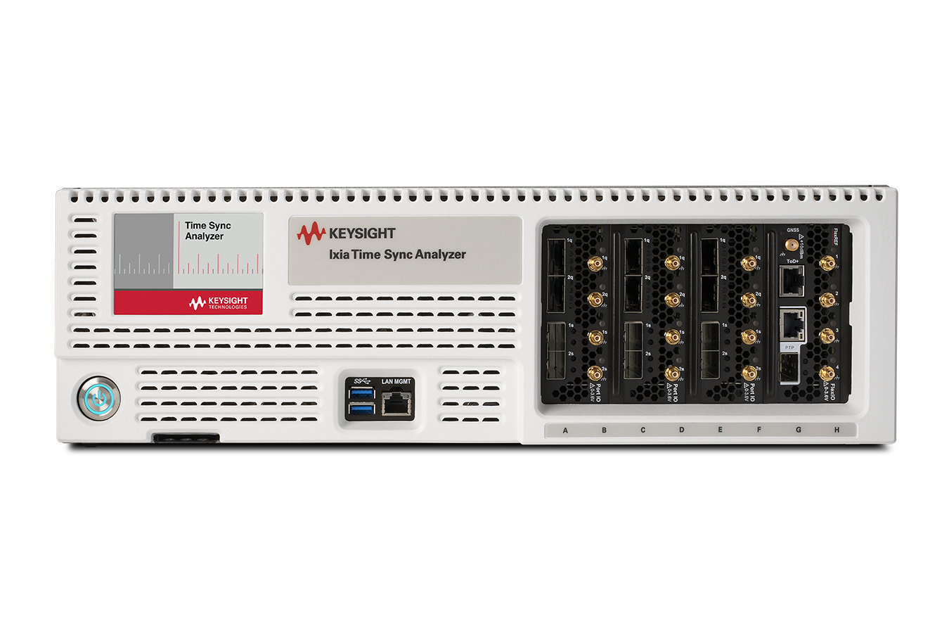
Synchronous Ethernet Clock Characterization Solution
See Block Diagram of Synchronous Ethernet Clock Characterization Solution


Explore Products in Our Synchronous Ethernet Clock Characterization Solution
-

![]()
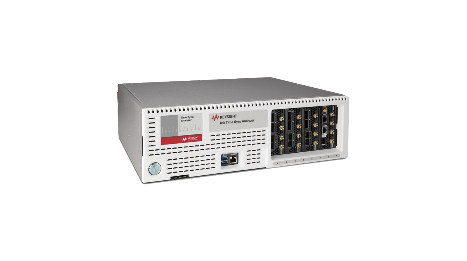
941-0120 Time Sync Analyzer Appliance and Base Software

Discover Resources and Insights
Discover Resources and Insights Additional Resources for Synchronous Ethernet Clock Characterization
Related Use Cases


-
![]()
Learn More
How to Validate Ethernet Interconnects in Data Centers
Validating Ethernet interconnects in data centers requires precise testing for reliability and performance. Learn how to ensure high-quality data transmission and error correction.
Learn More

-
![]()
Learn More
How to Emulate AI Data Center Workloads
Emulating AI data center workloads requires a consistent, repeatable and scalable testing methodology. Learn how to optimize infrastructure for AI training performance.
Learn More
-
![]()
Learn More
How to Validate 800GE Interoperability and Link Resilience
Validate 800GE interoperability, forward error correction behavior, throughput, and link resilience across optical and copper Ethernet interconnects for AI and data center networks.
Learn More

Get in Touch with One of Our Experts
Need help finding the right solution for you?