How to Select DC-Coupled or DC-Blocked Power Sensors for RF Measurements

Select the Appropriate Sensor Coupling
Selecting the appropriate power sensor requires understanding whether direct current (DC) is present together with the radio frequency (RF) signal at the measurement point. A DC-coupled sensor presents a direct electrical path at its input, while a DC-blocked sensor incorporates a blocking capacitor that prevents DC from reaching the sensing circuitry. Using an unsuitable sensor configuration can affect measurement performance and, when DC is present at the measurement point, may expose a DC-coupled sensor to conditions that can damage sensitive components. Engineers should therefore evaluate both the RF signal and any DC component before connecting the sensor.
The measurement setup typically includes an average power sensor connected to a compatible power meter and the RF source or device under test. Engineers determine whether DC voltage may be present on the RF path, review the sensor input configuration and operating limits, and select the appropriate coupling architecture before making the connection. Matching the sensor configuration to the electrical characteristics of the test point helps engineers obtain reliable average power measurements while reducing the risk of measurement errors or sensor damage.

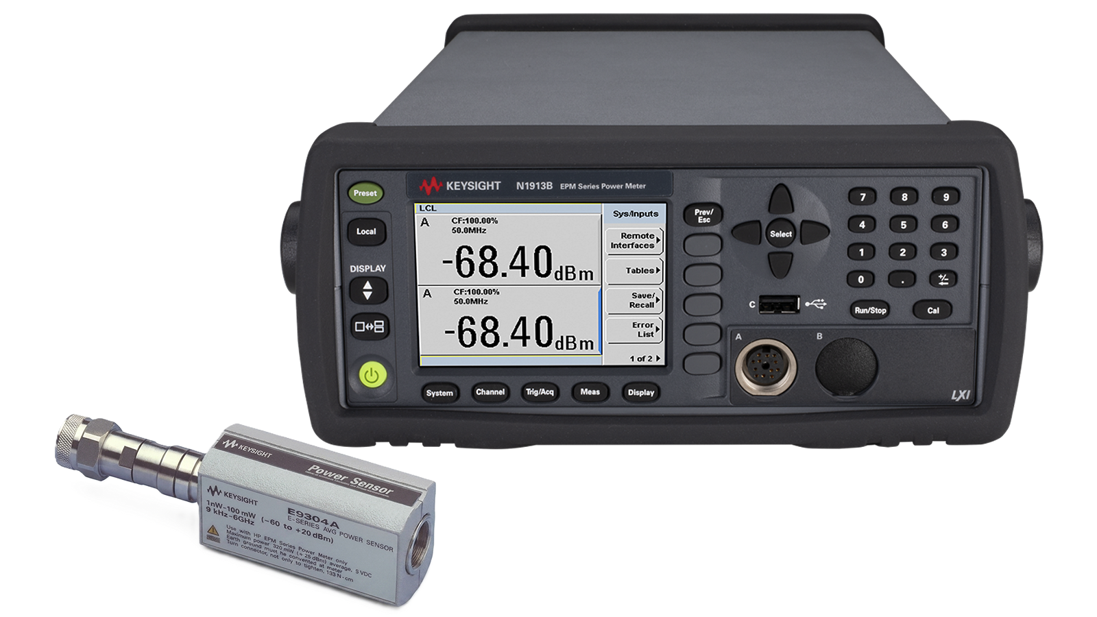
Average RF Power Sensor Selection Solution
See Block Diagram of Average RF Power Sensor Selection Solution


Explore Products for Our Average RF Power Measurement Solution
-

![]()
E9300A E-Series Average Power Sensor
-
![]()
N1913B EPM Series Single-Channel Power Meter


Discover Resources and Insights
Additional Resources for Average RF Power Measurements
Related Use Cases

-
![]()
Learn More
How to Calibrate Vector Network Analyzer Source Power with a USB Power Sensor
Calibrate vector network analyzer source power using a USB power sensor to correct power at the measurement plane across the test frequency range.
Learn More

-
![]()
Learn More
How to Maintain Signal Generator Output Power with External Leveling
Maintain radio frequency signal generator output power using a USB power sensor for external leveling and closed-loop power control.
Learn More
-
![]()
Learn More
How to Benchmark 5G Devices
Benchmarking a 5G device means subjecting it to a wide range of network signaling and radio channel conditions. Learn how to set up a test to emulate real-world network conditions and equipment to stress your 5G device and verify its performance.
Learn More

Get in Touch with One of Our Experts
Need help finding the right solution for you?