How to Find Worst-Case Island Clearing Time

Locate Worst-Case Clearing Time
A worst-case clearing time search starts from a validated resonant island operating point with real and reactive power closely balanced. After measuring the baseline anti-islanding test result, the reactive component of the emulated load is adjusted incrementally to move the island resonance to either side of line frequency. A controlled reactive impedance sweep evaluates conditions below and above the baseline value in small steps. At every point, the inverter is returned to the required pre-island operating state, residual grid current is checked, the grid connection is opened, and the elapsed time to shutdown is measured. This produces a repeatable data set showing how anti-islanding response changes as the resonant-load condition moves away from its initial tuning. The same acquisition and shutdown criteria are maintained at every step so changes in the measured result can be attributed to the programmed impedance offset.
The sweep continues until the measured clearing-time trend decreases on both sides of the maximum region. The test system can then identify the longest-duration points and repeat them to verify the result and investigate possible non-detection zone behavior. Automated sequencing helps maintain the same setup, operating-point verification, island transition, waveform acquisition, and timing calculation for every test point. For IEEE 1547.1 evaluation, the resulting curve shows clearing-time sensitivity to reactive-load changes instead of representing the inverter with only one nominal load condition. Maintaining consistent tuning and measurement throughout the sweep also reduces the influence of operator-dependent adjustments when comparing results across a large number of repeated island events. Trend plots, captured waveforms, and repeated maximum points can then be reviewed together to confirm that the longest measured clearing time is reproducible.

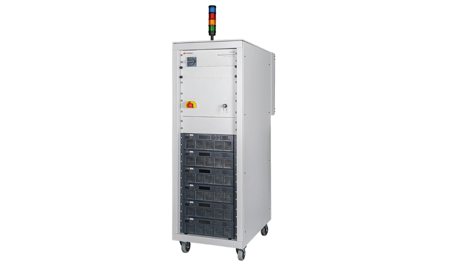
Worst-Case Clearing Time Test Solution
See Block Diagram of Worst-Case Clearing Time Test Solution


Explore Products in Our Worst-Case Clearing Time Test Solution
-

![]()
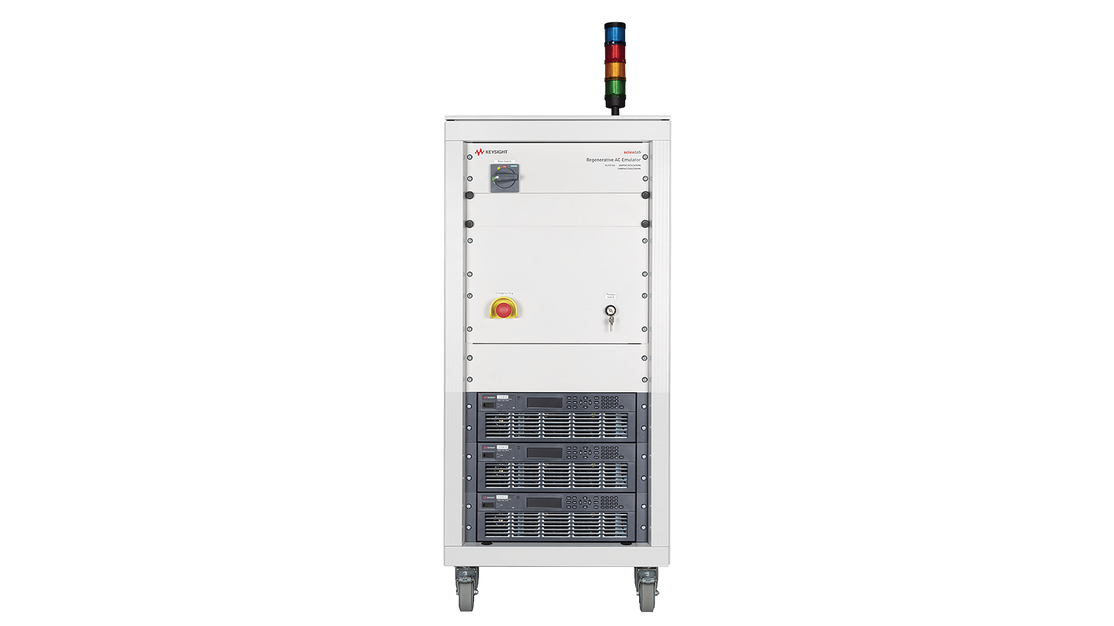
SL1201A Scienlab Regenerative AC Emulator, 600 VAC, 63 A, 30 kVA, 3‑Phase

Discover Resources and Insights
Additional Resources for Worst-Case Clearing Time Test
Related Use Cases


-
![]()
Learn More
How to Debug Inverter Anti-Islanding Detection Algorithms
Debug anti-islanding detection algorithms by reproducing controlled resonant island conditions, measuring inverter voltage and frequency response after grid isolation, and comparing shutdown behavior across changes in reactive loading and control settings.
Learn More

-
![]()
Learn More
How to Emulate Partial Shading Conditions
Simulate partial shading in PV systems to validate inverter performance, MPPT behavior, and solar array efficiency under real-world conditions.
Learn More
-
![]()
Learn More
How to Simulate Battery Power Accurately
Simulate battery power behavior using DC supplies to validate IoT device performance under real-world conditions.
Learn More

Get in Touch with One of Our Experts
Need help finding the right solution for you?