How to Characterize Pulsed RF Signal Power

Characterize Time-Gated Pulsed RF Power
Pulsed radio frequency (RF) power characterization requires a power meter, an appropriate peak and average power sensor, and a measurement connection to the signal under test. The measurement system samples the changing RF power envelope so that measurements can be positioned within defined portions of the pulse rather than averaged across the complete signal period. A time gate establishes the interval over which the meter calculates the selected power parameter. Triggering synchronizes acquisition with the pulse, while gate placement determines which portion of the waveform contributes to the result. Engineers can configure the measurement interval to examine the pulse independently from intervals between pulses and other portions of the repeating signal envelope.
Once the pulsed waveform is acquired, measurements within the selected gate can determine peak power, average power, and the relationship between peak and average levels. Multiple gates can be positioned at different locations in the waveform when measurements need to compare separate regions of the pulse or characterize changes in power over its duration. Time-referenced sampling also supports measurements such as pulse droop by comparing power levels at selected positions within the pulse envelope. The measurement process therefore combines trigger control, digital sampling, gate placement, and power calculations. Results are derived from the samples contained within each configured measurement interval, allowing specific portions of a repetitive RF pulse to be characterized independently.


Pulsed RF Power Characterization Solution
Block Diagram of Pulsed RF Power Characterization Solution


Explore Products in Our Pulsed RF Power Characterization Solution
-

![]()
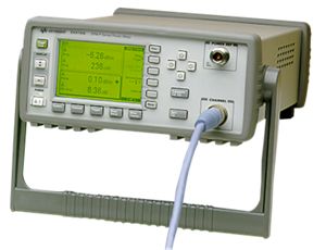
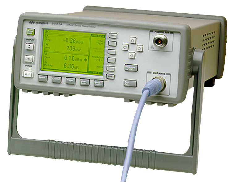
E4416A EPM-P Series Single-Channel Power Meter

Discover Resources and Insights
Additional Resources for Pulsed RF Power Characterization
Related Use Cases

-
![]()
Learn More
How to Perform Burst Power Measurement
Measure burst RF signal power using time-gated averaging with power meters, sensors, and automated control software for TDMA systems.
Learn More

-
![]()
Learn More
How to Measure RF Power During Rapid Amplitude Switching
Measure RF power during rapid amplitude transitions using a power meter, fast-response sensors, continuous acquisition, and automated measurement techniques.
Learn More
-
![]()
Learn More
How to Measure Average Power of Frequency-Hopping Signals
Measure average RF power of frequency-hopping signals using power meters, sensors, and time-aligned measurement techniques for accurate results.
Learn More

Get in Touch with One of Our Experts
Need help finding the right solution for you?