How to Characterize Power Supply Current Limits

Characterize Current Limit Behavior
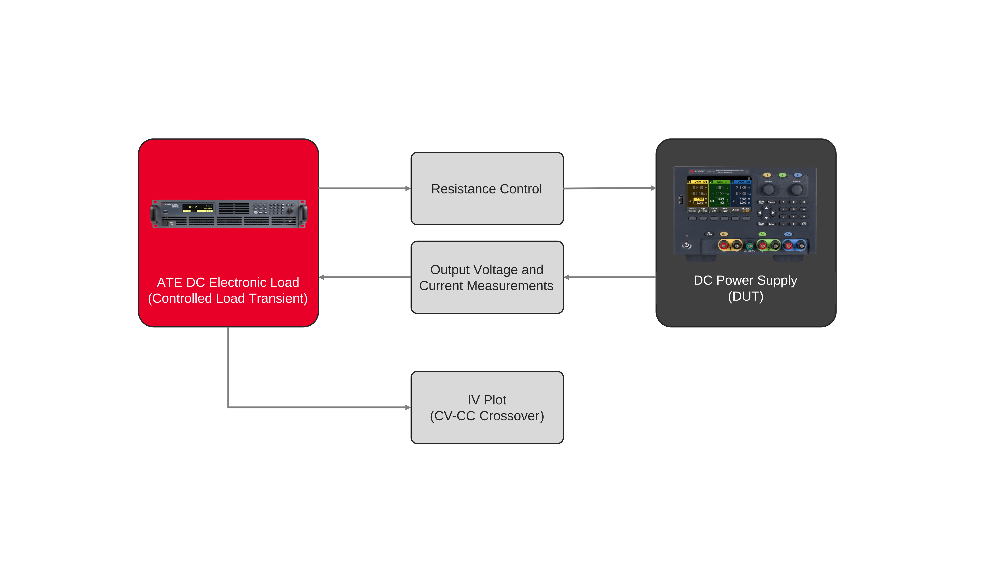
Characterizing power supply current limiting requires progressively increasing the load while monitoring the resulting output voltage and current. The setup includes a programmable DC electronic load connected to the power supply under test, with voltage and current measurements recorded throughout the load sweep. The test begins with a relatively high load resistance so the supply operates in constant-voltage (CV) mode while drawing minimal current. The electronic load then reduces the resistance in controlled steps, increasing the output current while the supply voltage is measured at each operating point.
As the load resistance decreases, the power supply eventually reaches its programmed current limit and transitions from constant-voltage operation into current-limiting behavior. The measured voltage-current data identifies the crossover region and shows how the supply regulates after reaching the current limit. A sharp crossover indicates a more defined transition into constant-current (CC) operation, while the shape of the voltage-current characteristic reveals the supply’s current-limiting behavior. Repeating the resistance sweep under controlled conditions provides a consistent method for characterizing the crossover point and current regulation across the required operating range.


Power Supply Current Limit Test Solution
See Block Diagram of Power Supply Current Limit Test Solution

Explore Products in Our Power Supply Current Limit Test Solution
-

![]()
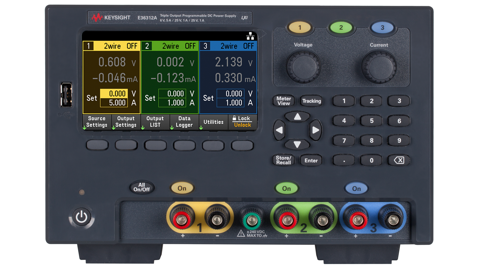
E36312A 80W Triple Output Power Supply, 6V/5A, 25V/1A, 25V/1A
-
![]()
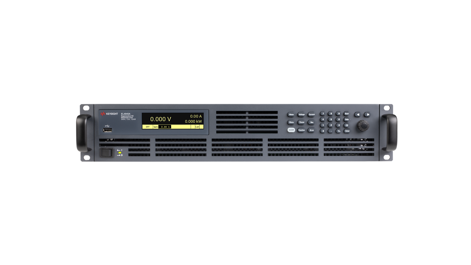
EL4946A Regenerative DC Electronic Load, 800V, 48A, 12kW

Discover Resources and Insights
Additional Resources for Power Supply Current Limit Test
Related Use Cases

-
![]()
Learn More
How to Validate Solar Inverter Maximum Power Point Tracking Efficiency
Validate solar inverter MPPT efficiency using solar array simulators to replicate real-world irradiance and optimize power tracking performance.
Learn More

-
![]()
Learn More
How to Analyze Grid-Tied Inverter Transient Response
Analyze inverter transient response under dynamic irradiance and grid conditions to ensure stability, performance, and compliance.
Learn More
-
![]()
Learn More
How to Test Solar Inverter Startup Behavior
Test inverter startup and shutdown behavior using solar array simulators to ensure reliable operation under varying irradiance and power conditions.
Learn More

Get in Touch with One of Our Experts
Need help finding the right solution for you?