Learn More
segmentation:campaign/Digital_General_Purpose,segmentation:product-category/Oscilloscopes_BERTs_AWGs,segmentation:product-category/Oscilloscopes_BERTs_AWGs/Oscilloscopes_upto_2GHz,segmentation:business-unit/CSG,keysight:product-lines/1a,segmentation:funnel/bofu,keysight:dtx/solutions/facets/design-and-test-product/oscilloscope---logic-analyzer,keysight:dtx/solutions/facets/workflow-stage/functional-test,keysight:dtx/solutions/facets/development-area/high-speed-digital,keysight:dtx/solutions/facets/industry/semiconductor,keysight:models/hd/hd304msosegmentation:campaign/Digital_General_Purpose,segmentation:product-category/Oscilloscopes_BERTs_AWGs,segmentation:product-category/Oscilloscopes_BERTs_AWGs/Oscilloscopes_upto_2GHz,segmentation:business-unit/CSG,keysight:product-lines/1a,segmentation:funnel/bofu,keysight:dtx/solutions/facets/design-and-test-product/oscilloscope---logic-analyzer,keysight:dtx/solutions/facets/workflow-stage/functional-test,keysight:dtx/solutions/facets/development-area/high-speed-digital,keysight:dtx/solutions/facets/industry/semiconductor,keysight:models/hd/hd304msosegmentation:campaign/Digital_General_Purpose,segmentation:product-category/Oscilloscopes_BERTs_AWGs,segmentation:product-category/Oscilloscopes_BERTs_AWGs/Oscilloscopes_upto_2GHz,segmentation:business-unit/CSG,keysight:product-lines/1a,segmentation:funnel/bofu,keysight:dtx/solutions/facets/design-and-test-product/oscilloscope---logic-analyzer,keysight:dtx/solutions/facets/workflow-stage/functional-test,keysight:dtx/solutions/facets/development-area/high-speed-digital,keysight:dtx/solutions/facets/industry/semiconductor,keysight:models/hd/hd304msosegmentation:campaign/Digital_General_Purpose,segmentation:product-category/Oscilloscopes_BERTs_AWGs,segmentation:product-category/Oscilloscopes_BERTs_AWGs/Oscilloscopes_upto_2GHz,segmentation:business-unit/CSG,keysight:product-lines/1a,segmentation:funnel/bofu,keysight:dtx/solutions/facets/design-and-test-product/oscilloscope---logic-analyzer,keysight:dtx/solutions/facets/workflow-stage/functional-test,keysight:dtx/solutions/facets/development-area/high-speed-digital,keysight:dtx/solutions/facets/industry/semiconductor,keysight:models/hd/hd304msosegmentation:campaign/Digital_General_Purpose,segmentation:product-category/Oscilloscopes_BERTs_AWGs,segmentation:product-category/Oscilloscopes_BERTs_AWGs/Oscilloscopes_upto_2GHz,segmentation:business-unit/CSG,keysight:product-lines/1a,segmentation:funnel/bofu,keysight:dtx/solutions/facets/design-and-test-product/oscilloscope---logic-analyzer,keysight:dtx/solutions/facets/workflow-stage/functional-test,keysight:dtx/solutions/facets/development-area/high-speed-digital,keysight:dtx/solutions/facets/industry/semiconductor,keysight:models/hd/hd304msosegmentation:campaign/Digital_General_Purpose,segmentation:product-category/Oscilloscopes_BERTs_AWGs,segmentation:product-category/Oscilloscopes_BERTs_AWGs/Oscilloscopes_upto_2GHz,segmentation:business-unit/CSG,keysight:product-lines/1a,segmentation:funnel/bofu,keysight:dtx/solutions/facets/design-and-test-product/oscilloscope---logic-analyzer,keysight:dtx/solutions/facets/workflow-stage/functional-test,keysight:dtx/solutions/facets/development-area/high-speed-digital,keysight:dtx/solutions/facets/industry/semiconductor,keysight:models/hd/hd304msosegmentation:campaign/Digital_General_Purpose,segmentation:product-category/Oscilloscopes_BERTs_AWGs,segmentation:product-category/Oscilloscopes_BERTs_AWGs/Oscilloscopes_upto_2GHz,segmentation:business-unit/CSG,keysight:product-lines/1a,segmentation:funnel/bofu,keysight:dtx/solutions/facets/design-and-test-product/oscilloscope---logic-analyzer,keysight:dtx/solutions/facets/workflow-stage/functional-test,keysight:dtx/solutions/facets/development-area/high-speed-digital,keysight:dtx/solutions/facets/industry/semiconductor,keysight:models/hd/hd304msosegmentation:campaign/Digital_General_Purpose,segmentation:product-category/Oscilloscopes_BERTs_AWGs,segmentation:product-category/Oscilloscopes_BERTs_AWGs/Oscilloscopes_upto_2GHz,segmentation:business-unit/CSG,keysight:product-lines/1a,segmentation:funnel/bofu,keysight:dtx/solutions/facets/design-and-test-product/oscilloscope---logic-analyzer,keysight:dtx/solutions/facets/workflow-stage/functional-test,keysight:dtx/solutions/facets/development-area/high-speed-digital,keysight:dtx/solutions/facets/industry/semiconductor,keysight:models/hd/hd304msosegmentation:campaign/Digital_General_Purpose,segmentation:product-category/Oscilloscopes_BERTs_AWGs,segmentation:product-category/Oscilloscopes_BERTs_AWGs/Oscilloscopes_upto_2GHz,segmentation:business-unit/CSG,keysight:product-lines/1a,segmentation:funnel/bofu,keysight:dtx/solutions/facets/design-and-test-product/oscilloscope---logic-analyzer,keysight:dtx/solutions/facets/workflow-stage/functional-test,keysight:dtx/solutions/facets/development-area/high-speed-digital,keysight:dtx/solutions/facets/industry/semiconductor,keysight:models/hd/hd304msosegmentation:campaign/Digital_General_Purpose,segmentation:product-category/Oscilloscopes_BERTs_AWGs,segmentation:product-category/Oscilloscopes_BERTs_AWGs/Oscilloscopes_upto_2GHz,segmentation:business-unit/CSG,keysight:product-lines/1a,segmentation:funnel/bofu,keysight:dtx/solutions/facets/design-and-test-product/oscilloscope---logic-analyzer,keysight:dtx/solutions/facets/workflow-stage/functional-test,keysight:dtx/solutions/facets/development-area/high-speed-digital,keysight:dtx/solutions/facets/industry/semiconductor,keysight:models/hd/hd304msosegmentation:campaign/Digital_General_Purpose,segmentation:product-category/Oscilloscopes_BERTs_AWGs,segmentation:product-category/Oscilloscopes_BERTs_AWGs/Oscilloscopes_upto_2GHz,segmentation:business-unit/CSG,keysight:product-lines/1a,segmentation:funnel/bofu,keysight:dtx/solutions/facets/design-and-test-product/oscilloscope---logic-analyzer,keysight:dtx/solutions/facets/workflow-stage/functional-test,keysight:dtx/solutions/facets/development-area/high-speed-digital,keysight:dtx/solutions/facets/industry/semiconductor,keysight:models/hd/hd304mso
How to Measure Power Rail Ripple
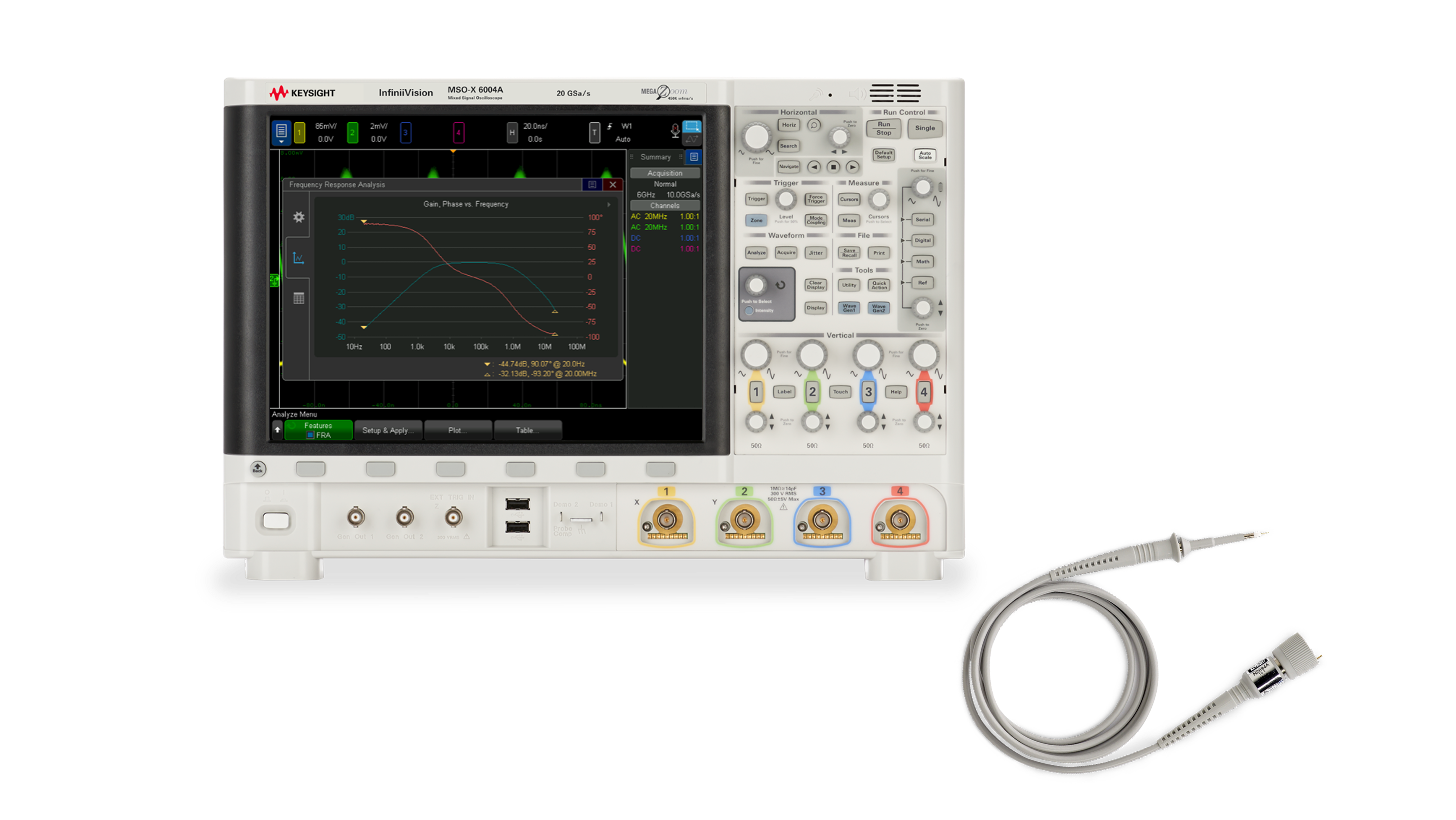
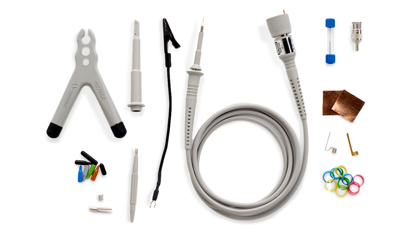
Learn how to measure ripple and noise on DC power rails with a low-noise oscilloscope setup, a dedicated power rail probe, and loading-aware techniques that keep measurement-induced distortion low.
Learn More