How to Characterize RF Power Sensor Mismatch Uncertainty

Mismatch Uncertainty Measurements
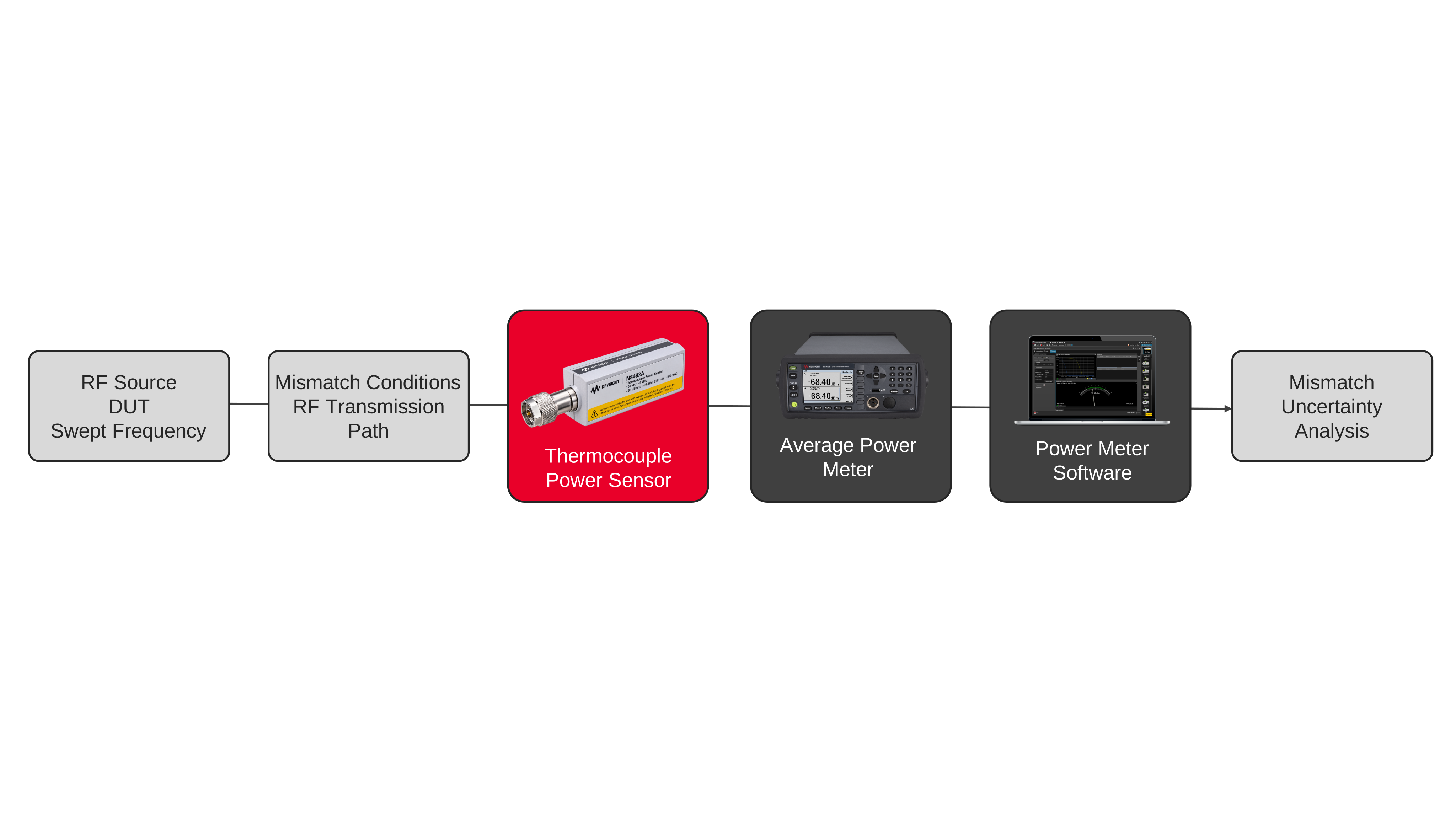
Radio frequency (RF) power sensor mismatch uncertainty measurements require broadband thermal sensing methods capable of maintaining stable impedance response across varying operating frequencies and signal conditions. The measurement setup typically includes a power meter, thermocouple power sensor, broadband signal source, calibrated attenuators, impedance-matched transmission paths, and synchronized acquisition controls to characterize standing wave interactions and reflected power behavior during swept-frequency validation workflows.
The measurement process evaluates the interaction between source impedance, sensor impedance, and transmission path mismatch conditions while continuously acquiring average power measurements across changing frequencies and operating levels. Acquisition, averaging, synchronization, correction factor application, logging, and statistical analysis techniques are used to characterize mismatch uncertainty behavior and quantify measurement variation caused by impedance discontinuities, reflected energy, and broadband standing wave effects during radio frequency subsystem validation testing.

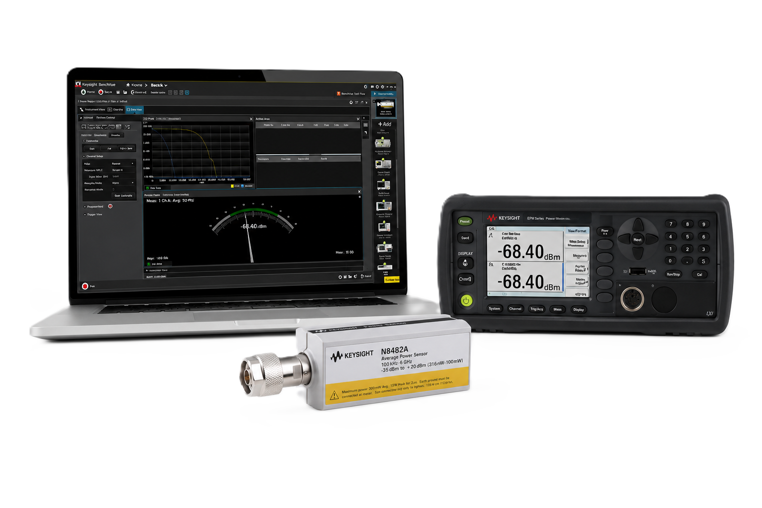
RF Power Sensor Mismatch Solution
See Block Diagram of RF Power Sensor Mismatch Solution

Explore Products in Our RF Power Sensor Mismatch Solution
-

![]()
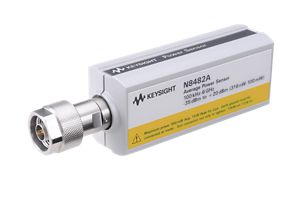
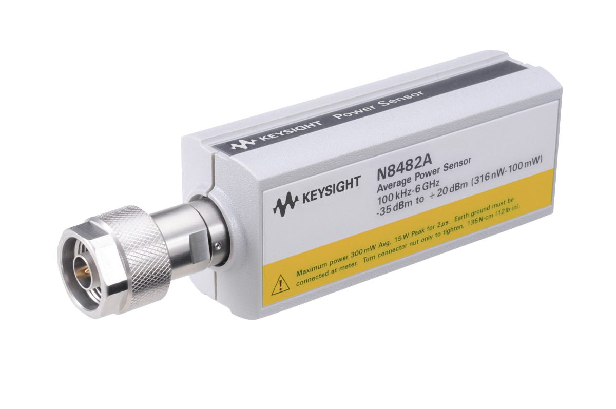
N8482A Thermocouple Power Sensors
-
![]()
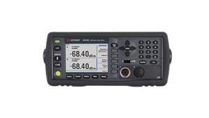
N1913B EPM Series Single-Channel Power Meter
-

![]()
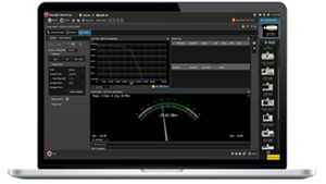
BV0007B PathWave BenchVue Power Meters/Sensors App


Discover Resources and Insights
Additional Resources for RF Power Sensor Mismatch Uncertainty
Related Use Cases
-
![]()
Learn More
How to Compare Thermal RF Power Across Multiple Frequency Bands
Compare thermal radio frequency power across multiple bands using a power meter and thermocouple sensor measurements.
Learn More

-
![]()
Learn More
How to Validate RF Power Sensor Frequency Response Compensation
Validate radio frequency power sensor frequency compensation using a power meter and thermocouple sensor measurements.
Learn More
-
![]()
Learn More
How to Minimize Standing Wave Effects in RF Power Measurements
Minimize standing wave effects using a power meter and thermocouple sensor measurement techniques.
Learn More

Get in Touch with One of Our Experts
Need help finding the right solution for you?